background image

9

IR Plus Assistive Listening System

Additional Devices

To create a full IR system, additional devices will need to be connected to the IR M1. Note that devices can be disconnected or 

connected to the IR M1 at any time without needing to shut off or power cycle the IR M1.
The IR E4 is an IR Emitter and up to four can be directly connected to the IR M1.

Device Types

Several types of devices may be plugged into the IR M1 modulator. Not all of these device types are valid and can indicate a 

problem with the IR + setup or device.

DEVICE TYPE

SHORT DESCRIPTION

MEANING

IR E4 Emitter

IR E4

Valid Device. An IR Emitter.

Unknown

UNKWN

This type of device is not recognized. There may be a short in 

the device that is preventing the system from detecting what it is.

Invalid

INVLD

This device is not connected in a usable manner. The IR + system 

may not have a required firmware update to recognize this 

device type.

None

---

Nothing is detected as being plugged into the port.

The device type can be viewed on the IR M1 website, or via the front panel and may be useful when troubleshooting.

Wiring and Cabling

CAT5e cables must be used for connecting devices. They are not required to be shielded. The maximum recommended cable 

length is 300 ft (91.4 m).
Each CAT5e cable connection from the IR M1 system to the IR E4 emitters carries the following signals:  

•  Baseband signals for 1 or 2 IR channels

•  +48V power supply for the IR E4

•  RS-485 bus communications

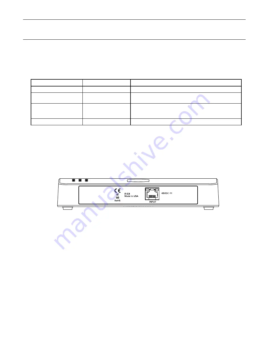
IR E4

Back Panel of IR E4

The IR E4 is connected to the IR M1 via a CAT5e cable. Once connected, any changes required can be made through the IR M1's 

webpage.
The IR E4 receives its power from the Ethernet cable and no additional power supply is required.

Note: Although the IR E4 receives power from an Ethernet cable, it does not follow the formal Power over Ethernet (PoE) standard�

Summary of Contents for IR E4

Page 1: ...IR Infrared and Wi Fi Assistive Listening System USER MANUAL MAN 273A ...

Page 2: ...el 7 Front Panel 7 Back Panel 8 Additional Devices 9 Device Types 9 Wiring and Cabling 9 IR E4 9 Installation Instructions 10 Determine Coverage Area 10 Determine Location 11 Network Cable Connection 11 Cable Connection to Emitters 11 Audio Source Connections 12 Multi Channel Sources 12 Avoiding Hum in the Audio as a Result of a Ground Loop 12 System Settings 13 Audio Settings 13 Server Descriptio...

Page 3: ...3 Audio Channel Menu 23 Port Menu 23 Device Detail Page 23 Locking the Front Panel 23 WaveCAST App 24 Connect to Wi Fi Network 24 Connecting the App to the Channel 24 Listening via the App 24 Note on Wi Fi Assist Smart Network Switching 24 Troubleshooting 24 Specifications 28 Mounting Options 29 Optional Receivers 29 Regulatory Statements 29 FCC 29 ISED 29 VCCI 29 IR M1 2 Year Warranty Statement 3...

Page 4: ...structions All other servicing should be referred to qualified service personnel Precautions 1 Power WARNING BEFORE TURNING ON THE POWER FOR THE FIRST TIME READ THE FOLLOWING SECTION CAREFULLY The unit is designed for use only with the line cord of the region in which it will be operated 2 Voltage Label Rear Panel A label located at the rear panel power connection indicates the DC power input for ...

Page 5: ...e d emploi Toute autre tâche d entretien ou de réparation doit être confiée à un technicien qualifié Précautions 1 Alimentation AVERTISSEMENT AVANT DE METTRE L APPAREIL EN MARCHE POUR LA PREMIÈRE FOIS LIRE SOIGNEUSEMENT LA SECTION QUI SUIT L amplificateur est conçu pour être utilisé uniquement avec un cordon d alimentation adapté à la région dans laquelle il sera utilisé 2 Étiquette de tension pan...

Page 6: ...nerates uses and can radiate radio frequency energy and if not installed and used in accordance with the instruction manual may cause harmful interference to radio communications Operation of this equipment in a residential area is likely to cause harmful interference in which case the user will be required to correct the interference at his own expense NOTICE A plasma monitor can degrade the audi...

Page 7: ...e displayed If you do not see an IP address check your network connection Write it down and go to a computer on the same network as the IR 9 In Chrome or Edge type the IP address into the URL bar A webpage for the IR system will load The default usename is admin and the default password is admin 10 Click the Audio tab and set the audio device type and desired settings for each audio channel 11 Cli...

Page 8: ...ce on CH A and an emitter with Audio Channel A enabled the built in IR emitter on the front panel will broadcast Audio Channel A on the appropriate IR Baseband Channel see IR Baseband Output on page 14 If either Audio Channel is not actively enabled on at least one IR device attached to the M1 the front panel s built in emitter will not transmit anything even if an audio source is present Back Pan...

Page 9: ...usable manner The IR system may not have a required firmware update to recognize this device type None Nothing is detected as being plugged into the port The device type can be viewed on the IR M1 website or via the front panel and may be useful when troubleshooting Wiring and Cabling CAT5e cables must be used for connecting devices They are not required to be shielded The maximum recommended cabl...

Page 10: ...decrease the coverage area The IR E4 will use full power single channel mode by default Single channel or dual channel mode and emitter output power can be selected using the system webpage Connect the number of E4 s needed to cover the space required Interference Most objects block infrared light The coverage area may be affected by direct indirect sunlight reflections on walls and room construct...

Page 11: ...is needed to configure some device settings after the system is set up An Ethernet connection alone will not allow the Wi Fi broadcast features to work a Wi Fi connection must be available on the network A network connection is not required for broadcasting over infrared Once a connection has been established an IP address will automatically be assigned to the IR M1 see the front panel section s F...

Page 12: ...E USING 1 4 CONNECTOR IN PHASE A106 UNBALANCED LINE USING 1 4 CONNECTOR A107 4 7 K 4 7 K SOURCE A SOURCE B CONNECTING TO A MULTI CHANNEL OR STEREO SOURCE A109 Multi Channel Sources By constructing a simple resistive mixer stereo or 3 channel sources can be connected to the IR Additional channels can be accommodated by adding a resistor for each source Note The Dante audio input will automatically ...

Page 13: ... from the IR M1 Changes to the input level will affect the level indicated by the front panel display when audio is present The gain can be adjusted from 60dB to 24dB Audio Presets The Audio Presets allow the user to quickly and easily configure the IR M1 for common applications The audio preset can only be adjusted via the Web Interface There are three pre configured to choose from Hearing Assist...

Page 14: ...ut to Emitter ports can be used to help troubleshoot issues but may be distracting if left on during normal usage These LEDs may be disabled on the via the Web Interface for attached devices but they cannot be disabled on the IR M1 Green Communication Active Flashes as long as there are communications ongoing over that port otherwise remaining dark Amber Channel Signals Present On the IR M1 the am...

Page 15: ... the front panel menu it is hidden on the main screen Main Menu on page 22 Restoring defaults from the web page will reset all settings except Network connectivity settings IP Address Subnet Mask IP Address Mode and Web Password This maintains connectivity between the Web Page and the IR M1 after the IR M1 reboots In the web interface this feature is under the Admin menu Web Control Interface The ...

Page 16: ...e on the status screen If a device has overheated the Temp field will show there is an error If a device is having an issue with power the power field may show an error There may or may not be additional information available for these types of errors and these errors likely cannot be automatically repaired Under Status if the device has detailed error information it will display in a red box unde...

Page 17: ...onnected Disabled and Disconnected Devices and Settings Transfer The settings screen will display the settings stored for the device usually connected to that port even if it is not currently physically connected via a CAT5e cable These default settings are stored by the IR M1 and are saved for an individual Output to Emitter port If a device is not currently connected to that port and a different...

Page 18: ...r updating and web page performance Audio Input Gain adjusts the audio volume Up or down adjustment buttons are used to set the gain The audio input source selects the type of audio source that is connected to the selected channel Audio Presets adjust the sound to specific settings to improve the audio quality depending on if you are broadcasting audio that is primarily voice music or for an audie...

Page 19: ...ng the WaveCAST app This image can be used to easily distinguish the content of your audio broadcast The image must be under 128kB and be in PNG or JPG format The image can be replaced at any time To completely remove the image the device must be fully restored to factory defaults via the front panel menu see Restoring Defaults on page 23 ...

Page 20: ...rmation before rebooting the device TTL can be modified if there is a need The recommended setting for the least latency is 1 but it can be set up to 31 This setting should not be adjusted without proper consideration for your system setup For each channel the security settings and the multicast information of the channel can be adjusted Secure Mode can be enabled or disabled and a 6 digit PIN num...

Page 21: ...interface will not reset the username or password For a full reset the reset will need to be performed via the front panel of the device See Restoring Defaults on page 23 for more information Updating or rebooting the device will make the website temporarily unavailable While the device is restoring a message warning you to not power off the device will display on the OLED screen Firmware Updates ...

Page 22: ... This icon does not indicate network availability The availability of WaveCAST Wi Fi audio is also displayed in text above the IR M1 s name This text can be highlighted using the right or left arrow buttons Once highlighted push the up or down arrow buttons to turn the Wi Fi Audio on or off If Wi Fi audio has been disabled the text on the front panel will say so Wi Fi audio can be enabled by scrol...

Page 23: ...nal information displays the connected device s name status used channels power level and LED light status The device name is not in a labeled column it is the first item in a row In the picture the device name is IR E4 When a channel is being used it will be listed under IR Chs If a channel is not being used there will be a line in that channel s place If a channel is actively broadcasting audio ...

Page 24: ...veCAST creates is not an internet connection It creates a network connection to the audio stream only Some phones expect network connections to provide internet access When the phone cannot reach the internet it may automatically try to switch to a network connection with an internet connection Sometimes the phone determines that the best internet connection is through a mobile data network This i...

Page 25: ... by the app Ch A or Ch B VU Meter does not show audio Make sure the IR M1 is plugged in Make sure the audio input is connected properly Make sure an active and adequate level audio signal is being sent to the IR M1 modulator Make sure your audio input is selected properly If you re using a microphone and the channel is set for Line In the audio level will be too low Try turning up the audio at the...

Page 26: ... type CMD A black box should come up and the cursor will be blinking 2 Type ping followed by a space followed by the IP address of the IR M1 and hit Enter If you see a reply from IP address this means the hardwired Ethernet path is OK If you see request timed out there is most likely a break in the wiring path between the computer and the IR M1 3 Try pinging the IP address of the router If you can...

Page 27: ...h the internet browser If you can change settings and get feedback on the web page or verify the change on the front display of the IR M1 you are now connected to and controlling the IR M1 8 Try re booting in this order the router the computer the IR M1 turn it off for 10 seconds then turn it back on Wait at least two full minutes for the IR M1 to re establish itself on the network Then try testin...

Page 28: ...table as audio input source for setup and diagnostics Remote Configuration Available through embedded website Headphone Output 2 1 4 headphone jacks on front panel for monitoring CH A and CH B audio inputs Emitter Output Jack Four RJ 45 ports for CAT5e cables provides 48VDC Power RS 485 communication and Baseband signals for IR transmission Operating requirements 0 50ºC ambient temperature non con...

Page 29: ...y approved by the party responsible for compliance could void your authority to operate the equipment ISED Innovation Science and Economic Development Canada Statement This equipment complies with IC RSS 102 radiation exposure limits set forth for an uncontrolled environment Operation is subject to the following two conditions 1 this device may not cause harmful interference and 2 this device must...

Page 30: ...ice technician Warranty does not cover normal wear and tear on the product or any other physical damage unless the damage was the result of a manufacturing defect Williams AV is not liable for consequential damages due to any failure of equipment to perform as intended Williams AV shall bear no responsibility or obligation with respect to the manner of use of any equipment sold by it This warranty...

Page 31: ...authorized service technician Warranty does not cover normal wear and tear on the product or any other physical damage unless the damage was the result of a manufacturing defect Williams AV is not liable for consequential damages due to any failure of equipment to perform as intended Williams AV shall bear no responsibility or obligation with respect to the manner of use of any equipment sold by i...

Page 32: ...info williamsav com www williamsav com 800 843 3544 INTL 1 952 943 2252 2020 Williams AV LLC MAN 273A ...

Reviews: