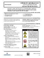
White Rodgers 50M56U-751 Installation Instructions Manual Download Page 1

FAILURE TO READ AND FOLLOW ALL INSTRUCTIONS CAREFULLY 
BEFORE INSTALLING OR OPERATING THIS CONTROL COULD CAUSE 
PERSONAL INJURY AND/OR PROPERTY DAMAGE.


 PARTS INCLUDED

•  50M56U-751 Integrated Furnace Control
•  9-Pin Adapter Harness
•  Flip Adapter Harness

•  4 – 1” Sheet Metal Screws
•  3 – 1/2” Sheet Metal Screws
•  Installation Instructions


 DESCRIPTION


 SPECIFICATIONS & TIMINGS

ELECTRICAL RATINGS:

Input Low Voltage: 

24 VAC, 60 Hz

Input Line Voltage: 

120 VAC, 60 Hz, 1

φ

Max Input Current: 

0.45 A @ 24 VAC

Relay Contact Ratings:


Gas Valve: 1.5 A, 0.6 PF @ 24 VAC


Ignitor Relay: 1.2 A @ 120 VAC


Inducer Relay:  2.8 A @ 120 VAC


Circulator Relay: 10 FLA, 25 LRA @ 120 VAC


Humidifier Load: 1.0 A @ 24 or 120 VAC


Electronic Air Cleaner: 1.0 A @ 120 VAC

Flame Current Requirements:


Minimum current to ensure flame detection:  
0.25 μA DC*


Maximum current for non-detection: 0.1 μA DC


Maximum allowable leakage resistance: 100 M 
ohms


* Measured with a DC ammeter


Flame Establishing Time:  0.8 seconds maximum


Flame Failure Response Time:   
2.0 seconds maximum 

OPERATING TEMPERATURE RANGE:

-40° to 176°F (-40° to 80°C)

HUMIDITY RANGE:

5 to 95% relative humidity (non-condensing)

PART NO. 37-7751001

2031

50M56U-751 with Black Cover

Carrier/ICP Integrated Single Stage 

120V Hot Surface Ignition Control Kit

INSTALLATION INSTRUCTIONS

50M56U-751 is an aftermarket direct replacement 
control kit for Carrier and ICP single stage furnace 
products with PSC blower motors. 

Risk of Electric Shock. 
Disconnect electric power 
to system until installation 
is complete. Do not use on 
circuit exceeding specified 
voltage. Higher voltage will 
damage control and could 
cause shock or fire hazard.

This control is not intended 
for use in locations where 
it may come in contact with 
water.

May cause flame rollout. 
Shut off main gas to 
heating system until 
installation is complete.

TWINNING:  50M56U-751 can be twinned. The other 
control must also be a 50M56U-751 with Black 
cover to ensure proper functionality.

AGENCY APPROVALS: 

UL USA / Canada

GASES APPROVED: 

Natural, Manufactured, Mixed,  Liq-

uid Petroleum, and LP Gas Air Mixtures.

emerson.com/white-rodgers

Summary of Contents for 50M56U-751

Page 1: ...0 8 seconds maximum Flame Failure Response Time 2 0 seconds maximum OPERATING TEMPERATURE RANGE 40 to 176 F 40 to 80 C HUMIDITY RANGE 5 to 95 relative humidity non condensing PART NO 37 7751001 2031 50M56U 751 with Black Cover Carrier ICP Integrated Single Stage 120V Hot Surface Ignition Control Kit INSTALLATION INSTRUCTIONS 50M56U 751 is an aftermarket direct replacement control kit for Carrier a...

Page 2: ... result in a miswiring that will cause a Limit Rollout Switch Open Error Code 33 and eventually a Limit Rollout Switch Lockout Code 13 The 11 pin inline connections for these applications are reversed or flipped 1 for 1 from the standard pinout To allow for this the Flip harness connects pin 1 on the control to pin 11 in the furnace Pin 2 on control to Pin 10 in the furnace etc 9 Pin Adapter Harne...

Page 3: ...eed wires are attached to the SPARE terminals Apply wire ties as needed to secure wiring 7 Verify Heat ON delay Constant Fan Speed Heat OFF Delay and Cool OFF Delay settings as described in the Configuration section 8 Reinstall unit access panels and reconnect electric power Restore gas supply to the unit 9 Verify unit operation in heating cooling and fan only mode Tabs For OEM direct mounting whe...

Page 4: ...nnected on Pin 3 of the 11 Pin main harness connector See the Wiring Diagram for additional details on connections specific to your application Enter Self Test immediately after control power up by Double pressing the FAULT RECALL button while LED rapid flashes green NOTE Control will terminate Self Test mode if any system fault occurs Control will ignore any active thermostat calls during Self Te...

Page 5: ...HT BLU FRS1 LS1 DSS BVSS WHEN USED GAS VALVE WHT RED WHT RED GRN YEL FRS2 LS2 WHEN USED WHEN USED 1 2 3 4 5 6 7 8 9 10 11 1 2 3 4 5 6 7 8 9 10 11 FLAME SENSOR PRESSURE OUT SEE 11 PIN DETAIL PRESSURE IN GAS VALVE GND LIMIT OUT SEE 11 PIN DETAIL LIMIT IN SEE 11 PIN DETAIL GAS VALVE OUT SEE 11 PIN DETAIL DESCRIPTION 11 PIN FUNCTIONS BLU PIN 3 INDUCER GROUND FRS1 LS1 DSS BVSS WHEN USED GAS VALVE FLAME...

Page 6: ... presence of a 24V signal no dehumidify demand and absence of a 24V signal dehumidify demand Dehumidify demand with a Y1 input runs the blower at the low cool speed selected by dipswitch SW1 2 heat speed is default Dehumidify demand with a Y Y2 input runs the blower at the cool speed for 10 minutes then reduces the blower speed from cool to low cool for 10 minutes then returns to the cool speed fo...

Page 7: ...the number of long flashes Example Ignition failure would display on the Red LED as 3 short flashes followed by 4 long flashes Fault Recall When the control is in standby mode press and hold the FAULT RECALL button approximately 3 5 seconds until the solid green LED turns off then release the button NOTE While displaying the stored fault codes the control will ignore any new call for heat cool or ...

Page 8: ...emerson com white rodgers Emerson and White Rodgers are trademarks of Emerson Electric Co 2020 Emerson Electric Co All rights reserved TECHNICAL SUPPORT 1 888 725 9797 ...

Page 9: ...e flamme 2 0 secondes maximum PLAGE DE TEMPÉRATURES DE MARCHE 40 à 176 F 40 à 80 C PLAGE D HUMIDITÉ 5 à 95 d humidité relative sans condensation NO DE PIÈCE 37 7751001 2031 50M56U 751 avec couvercle noir Trousse de commande d allumage de surface chauffante 120 V mono étage intégré Carrier ICP DIRECTIVES D INSTALLATION La commande 50M56U 751 est une trousse de commande de rechange universelle du ma...

Page 10: ...rrupteur de fin de course débordement Code 33 et finit par un verrouillage de l interrupteur de fin de course débordement Code 13 Les branchements intégrés à 11 broches de ces applications sont inversés 1 pour 1 à partir de la fiche normale Pour permettre ceci la broche 1 du faisceau d inversion sur la commande se branche sur la broche 11 de la fournaise la broche 2 de la commande sur la broche 10...

Page 11: ...E RÉSRV Installez des serre fils au besoin pour sécuriser le câblage 7 Vérifiez les paramètres Délai de mise en marche du chauffage Vitesse de ventilateur constante Délai d arrêt du chauffage et Délai de mise en marche de la climatisation dans la section Configuration 8 Réinstallez les panneaux d accès de l appareil et reconnectez l alimentation électrique et l alimentation de gaz de l appareil 9 ...

Page 12: ...oche 3 du connecteur de faisceau à 11 broches Consultez le Schéma de câblage pour obtenir des détails supplémentaires sur les branchements de votre application Passez à l auto test immédiatement après la mise sous tension de la commande comme suit Cliquezdeuxfoissurlebouton FAULTRECALL RAPPEL DEPANNE pendantquelaDELclignoterapidementenvert REMARQUE La commande mettra fin au mode auto test en cas d...

Page 13: ...GRN YEL FRS2 LS2 SI UTILISÉ SI UTILISÉ 1 2 3 4 5 6 7 8 9 10 11 1 2 3 4 5 6 7 8 9 10 11 CAPTEUR DE FLAMME PRESSION SORTIE VOIR LE DÉTAIL DE LA BROCHE 11 PRESSION ENTRÉE MALT VANNE À GAZ LIMITE DE SORTIE VOIR LE DÉTAIL DE LA BROCHE 11 LIMITE D ENTRÉE VOIR LE DÉTAIL DE LA BROCHE 11 VANNE À GAZ SORTIE VOIR LE DÉTAIL DE LA BROCHE 11 DESCRIPTION FONCTIONS CONNECTEUR À 11 BROCHES BLU BROCHE 3 MALT DE L I...

Page 14: ...déshumidification borne DHUM La fonction DHUM suit une logique inversée en ce qu un signal 24 V aucune commande de déshumidification et l absence de signal 24 V commande de déshumidification Une commande de déshumidification avec une entrée Y1 active le ventilateur à la vitesse de basse climatisation sélectionnée par le commutateur DIP SW1 2 la vitesse de chauffage est la vitesse par défaut Une co...

Page 15: ...de courts clignotements le deuxième chiffre est le nombre de longs clignotements Exemple La défaillance de l allumage s affiche sur la DEL rouge par 3 courts clignotement suivis de 4 longs clignotements Rappel de panne Lorsque la commande est en mode attente aucune demande de chauffage ni climatisation enfoncez et tenez le bouton FAULT RECALL environ 3 5 secondes jusqu à ce que la DEL verte contin...

Page 16: ...emerson com white rodgers Emerson et White Rodgers sont des marques de commerce d Emerson Electric Co 2020 Emerson Electric Co Tous droits réservés SOUTIEN TECHNIQUE 1 888 725 9797 ...

Reviews: