background image

18

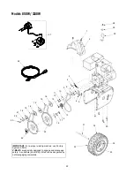
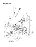
Models 850W / 1150W

14

10

2

14

12

16

3

20

58

66

61

60

63

67

65

57

58

55

54

8

17

11

22

21

18

4

1

11

15

19

52

7

14

49

42

27

36

44

30

28

32

44

48

10

23

38

35

35

39

9

43

26

25

31

40

41

9

50

24

37

31

45

9

51

40

46

47

53

59

29

68

69

69

27

82

70

72

72

73

27

68

71

74

27

56

64

76

77

78

79

11

15

75

81

27

83

80

13

13

For Reference Only

For Reference
Only

Summary of Contents for Snow Boss 1150W

Page 1: ...the engine s exhaust system is equipped with a spark arrester meeting applicable local or state laws if any If a spark arrester is used it should be maintained in effective working order by the operat...

Page 2: ...from your local authorized White Outdoor dealer You can locate the model number by looking at the lower frame cover on the rear of your snow thrower A sample model plate is explained below For future...

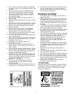
Page 3: ...res and other foreign objects which could be tripped over or thrown by the auger impeller 2 Always wear safety glasses or eye shields during operation and while performing an adjustment or repair to p...

Page 4: ...nts and accessories approved by the manufacturer e g wheel weights tire chains cabs etc 20 If situations occur which are not covered in this manual use care and good judgment Contact your dealer or te...

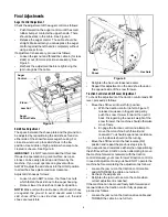
Page 5: ...ly until it locks over the lower handle Look at the lower rear of the snow thrower frame to be sure all the cables are aligned with the cable roller guides Secure the upper handle and lower handle wit...

Page 6: ...ground to avoid uneven wear on the skid shoes When one side does wear out the skid shoes are reversible Figure 6 Retighten the hex nuts loosened earlier Repeat this adjustment on the skid shoe found...

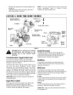
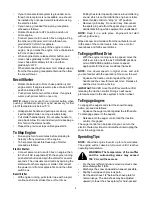
Page 7: ...ve control is located on the left handle Squeeze the control grip to engage the augers Release to stop the snow throwing action Traction control must also be released See Figure 7 Chute Tilt Control T...

Page 8: ...l Fill up Service the engine with gasoline and oil as instructed in the separate engine manual packed with your snow thrower Read instructions carefully WARNING Use extreme care when handling gasoline...

Page 9: ...box Recoil Starter With engine running pull starter rope with a rapid continuous full arm stroke three or four times Pulling the starter rope will produce a loud clattering sound which is not harmful...

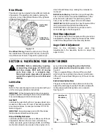
Page 10: ...itions of the shift lever With the traction control engaged the friction wheel must contact the drive plate See Figure 8 Figure 8 If adjustment is necessary Loosen the jam nut on the traction drive ca...

Page 11: ...moving parts have come to a complete stop Disconnect spark plug wire and ground it against the engine to prevent unintended starting Lubrication Engine Refer to the separate engine manual packed with...

Page 12: ...s and hex lock nuts If you hit a hard foreign object or ice jam the snow thrower is designed so that the bolts may shear Refer to Figure 12 If the augers will not turn check to see if the bolts have s...

Page 13: ...friction wheel disc See Figure 14 Back out the stop bolt until the support bracket rests on the auger pulley See Figure 15 Slip the belt between the friction wheel and drive disc Remove and replace th...

Page 14: ...Fuel left in engine for extended periods deteriorates and will cause starting problems If unit is to be stored over 30 days prepare for storage as follows Remove gasoline from carburetor and fuel tank...

Page 15: ...or have the carburetor adjusted by an authorized engine service dealer Excessive vibration 1 Loose parts or damaged auger 1 Stop engine immediately and disconnect spark plug wire Tighten all bolts and...

Page 16: ...16 Notes...

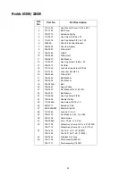
Page 17: ...Key 3 16 x 5 8 6 715 0143 Spring Spiral Pin 25 x 1 25 7 717 0528 Worm Gear 20 tooth 8 717 0526 Worm Shaft 9 718 0186 Thrust Collar 10 721 0325 Grease Plug 11 721 0327 Grease Seal 12 736 0351 Flat Was...

Page 18: ...54 8 17 11 22 21 18 4 1 11 15 19 52 7 14 49 42 27 36 44 30 28 32 44 48 10 23 38 35 35 39 9 43 26 25 31 40 41 9 50 24 37 31 45 9 51 40 46 47 53 59 29 68 69 69 27 82 70 72 72 73 27 68 71 74 27 56 64 76...

Page 19: ...lange Keeper 39 731 1300A Lower Chute 40 731 1313C Cable Guide Chute Tilt 41 731 1320 Upper Chute 42 731 2279 Motor Cover Chute Rotation 43 736 0159 5 16 Washer 44 736 0242 Belleville Washer 45 736 05...

Page 20: ...20 Models 850W 1150W 1 2 3 4 5 6 7 8 9 10 11 12 14 15 13 16 10 21 22 23 25 23 22 26 18 27 28 13 30 31 32 33 16 18 35 34 36 37 38 39 41 40 42 17 40 39 29 24 20 9 19...

Page 21: ...784 5038B Skid Shoe 31 736 0242 Bell Washer 32 712 3010 Hex Nut 5 16 18 33 784 5579A Shave Plate 850W 784 5575 Shave Plate 1150W 34 710 0260 Carriage Bolt 5 16 18 x 62 35 684 0065 Impeller Assembly 36...

Page 22: ...19 19 16 16 16 20 21 22 23 24 25 26 27 28 29 30 31 32 33 34 35 IMPORTANT For a proper working machine use Factory Approved Parts V BELTS are specially designed to engage and disengage safely A substi...

Page 23: ...756 0569 Pulley Half 17 736 0242 Bell Washer 18 736 0505 Flat Washer 19 754 0430A Belt 20 756 0967 Auger Pulley 21 736 0247 Flat Washer 3 8 x 1 25 OD 22 736 0331 Bell Washer 23 710 0696 Hex Cap Screw...

Page 24: ...37 33 37 10 9 13 1 34 26 31 30 16 9 43 17 34 46 34 18 19 6 39 18 24 40 34 32 14 20 32 35 38 45 40 34 32 38 32 20 14 9 48 5 7 49 36 47 36 47 11 41 42 11 9 43 16 30 9 51 13 9 26 34 4 25 7 54 55 57 53 21...

Page 25: ...LH 32 736 0351 Flat Washer 33 736 0626 Flat Washer 34 737 0170 Lubricant 6 in 1 35 737 0318 Grease 36 738 0924 Shoulder Screw 37 741 1111 Hex Flange Bearing 38 741 0598 Hex Flange Bearing 39 741 0600...

Page 26: ...26...

Page 27: ...27...

Page 28: ...ese items b Routine maintenance items such as lubricants filters blade sharpening and tune ups or adjustments such as brake adjustments clutch adjustments or deck adjust ments and normal deterioration...

Reviews: