Common Mode Rejection Ratio Tester | User Manual
WHALETEQ
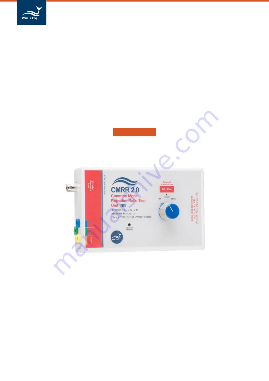
Common Mode Rejection Ratio Tester
(CMRR 2.0)
User Manual
(
Revision 2020-09-03
)
Page 1: ...Common Mode Rejection Ratio Tester User Manual WHALETEQ Common Mode Rejection Ratio Tester CMRR 2 0 User Manual Revision 2020 09 03 ...
Page 2: ...2 ECG Breakout Boxes 4 3 Set up 5 3 1 Environment noise reduction 5 4 Calibration 6 5 Principle of the CMRR test 9 5 1 Common mode rejection ratio explained 9 5 2 Common mode rejection in ECG equipment 9 5 3 Test equipment 10 6 Operation 12 7 Warnings Cautions Notes 14 8 Specifications 15 9 Contact details 15 ...
Page 3: ...external electrode connections to the imbalance terminal Elimination of these switches greatly simplifies the design of the CMRR box The box includes a step up transformer to allow a normal signal generator to be used The tests in IEC 60601 2 25 2011 IEC 60601 2 27 and IEC 60601 2 51 require a 20Vrms supply and most function generators are limited to 7Vrms This feature can be bypassed if desired b...
Page 4: ...or connecting the CMRR Box to test the ECG device use the ECG breakout box provided as explained on the following page Alternately the ECG device under test can be directly connected to CMRR Box using a male D15 connector The pin outs are The imbalance can be determined by external connections simulating the ECG breakout boxes on the following page 01 RA 06 V2 11 CMRR inner box 02 LA 07 V3 12 DC o...
Page 5: ...breakout box is used which shorts 9 terminals to the inner shield except RL N and Imbalance with DC terminal The effective circuit is Imbalance terminal 9 terminals RA LA LL V1 V6 RL N 47nF The test circuit in IEC 60601 2 47 2001 and ANSI AAMI EC 13 is the same except that all lead electrodes have the 51k 47nF except one which is directly connected to the inner shield This has the effective circui...
Page 6: ...nch or metal sheet underneath the ECG device under test the WhaleTeq CMRR test unit and also connecting together the ground as shown Metal bench metal sheet or foil With this set up turn the ECG device under test to maximum sensitivity turn off the ac filters if possible and with the function generator supply OFF confirm that the noise indication is 1mm 0 1mVpp ECG Device Under test Frame ground o...
Page 7: ...100pF 5 In general traceability for capacitance is not easy to obtain An alternate method involves using the 27kΩ resistor also used for verifying the WhaleTeq Single channel system With the 27kΩ connected between RA and ground the voltage should drop to At 20Vrms 50Hz 16 97mVrms 10 At 20Vrms 60Hz 20 35mVrms 10 At 20Vrms 200Hz 67 9mVrms 10 A test supply of 200Hz is recommended to minimize the infl...
Page 8: ...adjustment The adjustment capacitor can be adjusted using a small screw driver The adjustment uses a half turn capacitor 5 30pF or in later units 6 50pF without an end stop meaning that if it is continued in one direction the voltage will start to increase again Use small incremental adjustments and allow the voltage to stabilize after adjustment It is recommended to use a metal screw driver for g...
Page 9: ...nF will be loaded by 50 0 500 by a 27kΩ resistor A capacitance error of 10 corresponds to variation of 47 8 and 52 2 loading by a 27kΩ resistor RA FG set to 80Hz 51kΩ Imbalance with DC Sinewave e g 1Vrms 47nF 27kΩ Multimeter Vrms RL If all values are perfect a 27kΩ resistor will load the output by exactly 50 compared to the unloaded value when using 80Hz DC offset 300mV 1 This can be measured betw...
Page 10: ...alance as the imbalance also upsets the measurement circuit CMRR for multimeters is typically specified with a 1kΩ imbalance 5 2 Common mode rejection in ECG equipment ECG equipment can be subjected to a fairly high common mode voltage from mains noise 50 60Hz and can have a much higher impedance imbalance The test in the standard simulates 10Vrms with an imbalance of 51kΩ 47nF and allows an indic...
Page 11: ...1 the test requires a 20Vrms source This can be sourced from the mains supply but for those wishing to test at various frequencies and have good control over the applied voltage use of a function generator is more convenient A function generator is usually limited to 7 1Vrms 20Vpp To assist with this WhaleTeq s equipment has a small transformer built into the equipment which allows the voltage to ...
Page 12: ...Common Mode Rejection Ratio Tester User Manual 11 suspected reason is that the right leg drive is unable to respond correctly if there is other higher frequency noise around ...
Page 13: ...f Monitor and GND terminals Keep the leads and meter on the earthed plane Verify that with the source off the indication on DMM the meter is 0 5mV If not check adjust 0 5mVrms grounding remove nearby noise sources or choose a different location If more than 0 5mV remains record as a potential source of error3 Earthed plane Some meters have the ability to filter out higher frequency noise above 1kH...
Page 14: ...set up RA to RA LA to LA etc keeping the ECG leads above the earthed plane With the source off confirm indication on the ECG is less than 1mm peak to valley peak to peak This is a double check that the environment noise is sufficiently low ECG under test Earthed plane 8 Turn on the source connect RA to the imbalance terminal and measure the indication on all leads Lead I II III V1 V6 Note With RA ...
Page 15: ...enerator input is used and the frequency is different to that of the environment e g input 50Hz environment 60Hz the result on the ECG may show some beating with the residual noise from the environment This beating should be at a frequency equal to the difference in frequencies e g 10Hz and not greater in amplitude than the residual noise when no input is applied If the set frequency is nominally ...
Page 16: ...F 100pF 5 5 Imbalance impedance R 51kΩ 51kΩ 1 0 5 Imbalance impedance C 47nF 47nF 5 5 DC offset Internal battery powered 300mV 1 Up to 50hrs with intermittent use 0 3 Environment Intended for normal laboratory environment The selection of critical components is known to be stable in the range shown The 50MΩ divider may be affected by high humidity in excess of 85 15 30 C 10 75 RH Assured by select...