Whalen XLDEC54-NV Assembly Instructions Manual Download Page 1

THIS INSTRUCTION BOOKLET CONTAINS 

IMPORTANT

 SAFETY INFORMATION.  

PLEASE READ AND KEEP FOR FUTURE REFERENCE. 

Whalen Furniture Mfg., Inc.  

                     Page 1 


       Factory No. 33-10944
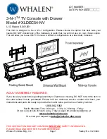


3-N-1

TM

 TV Console with Drawer 

Model # XLDEC54-NV 

U.S. Patent 8,561,551 


This item is designed to be a 3-in-1 configuration. Please choose the option that best suits your 
needs. DO NOT discard any of the hardware or parts that you will not use on your chosen option. 
This will allow you to use this TV Console in different configurations at a later date, if desired.


ADULT ASSEMBLY REQUIRED 


If you have any questions regarding assembly or if parts are missing, DO NOT return this item to 
the store where it was purchased. Please call our customer service number and have your 
instructions and parts list ready to provide the model name, part name or factory number:  


1-866-942-5362 

Pacific Standard Time: 8:30 a.m. - 4:30 p.m., Monday - Friday 

Or visit our web site 24 hours a day, 7 days a week for product assistance at  

www.whalenfurniture.com 

Or e-mail your request to


[email protected] 


LOT NUMBER:      


DATE PURCHASED:    /    /  

Summary of Contents for XLDEC54-NV

Page 1: ...llow you to use this TV Console in different configurations at a later date if desired ADULT ASSEMBLY REQUIRED If you have any questions regarding assembly or if parts are missing DO NOT return this item to the store where it was purchased Please call our customer service number and have your instructions and parts list ready to provide the model name part name or factory number 1 866 942 5362 Pac...

Page 2: ...ACKET MAXIMUM LOAD 135 lb 61 2 kg MAXIMUM LOAD 50 lb 22 6 kg GENERAL INFORMATION TIPS and TRICKS THIS UNIT IS NOT INTENDED FOR USE WITH CRT TVS USE ONLY WITH FLAT PANEL TVS AND AUDIO VIDEO EQUIPMENT MEETING RECOMMENDED SIZE AND WEIGHT LIMITS NEVER USE WITH LARGER HEAVIER THAN RECOMMENDED FLAT PANEL TVS OR EQUIPMENT TO AVOID INSTABILITY PLACE FLAT PANEL TV IN THE CENTER OF THE UNIT CRT TVS IMPROPER...

Page 3: ... all listed parts and hardware are present before beginning assembly A Top Shelf Frame 1 B Middle Shelf Frame 1 C Bottom Shelf Frame 1 D Spine Assembly 1 E Left Metal Leg 1 F Right Metal Leg 1 G Left Leg Top Rail 1 H Left Wood Leg 1 I Right Leg Top Rail 1 J Right Wood Leg 1 K Drawer Box 1 L Top Glass 1 M Glass Shelf 1 N Swiveling Bracket 1 O Mounting Frame 1 P Monitor Bracket 2 Q Cable Wheel 2 1 S...

Page 4: ...0 Concrete Anchor 11 2 1 2 Lag Bolt 12 Large Flat Washer 13 Spine End Cap 4 4 4 1 extra 1 14 Handle and Bolts M4 Allen Wrench Touch up Pen Tipping Restraint Hardware Kit 1 2 2 1 Inside Plastic Bag TV Mounting Kit M4 x 12 Bolt 4 M4 x 30 Bolt 4 M5 x 12 Bolt 4 M5 x 30 Bolt 4 M6 x 12 Bolt 4 M6 x 35 Bolt 4 M8 x 16 Bolt 4 M8 x 40 Bolt 4 M4 Lock Washer 4 M5 Lock Washer 4 M6 Lock Washer 4 M8 Lock Washer 4...

Page 5: ... will make the assembly easier 1 Unpack the unit and confirm that you have all the hardware and required parts 2 Locate the Left Leg Top Rail G on a scratch free surface with the threaded inserts facing up as shown 3 Align and attach Left Metal Leg E to the Left Leg Top Rail G using two 1 1 2 Bolts 6 as shown Make sure that the front edges are even with each other 4 Fasten the Left Wood Leg H to t...

Page 6: ...or replacement parts or assistance 1 866 942 5362 Whalen Furniture Mfg Inc Page 6 Factory No 33 10944 Assembly Instructions 5 Repeat the same procedure to assemble the Right Legs As shown above 1 1 2 Bolt 5 used in this step 6 6 6 J ...

Page 7: ...ting two 3 4 Bolts 3 with Lock Washers 7 and Flat Washers 8 through the U shape bracket and screw in place Make sure that the end brackets will face the bottom of the unit 8 Fasten the Middle and Bottom Shelf Frames B and C to the Spine D using two 1 1 8 Bolts 4 in each Make sure that the inside corner brackets on the Middle Shelf Frame will face up when the unit is turned upright Lock Washer 2 us...

Page 8: ...Furniture Mfg Inc Page 8 Factory No 33 10944 Assembly Instructions 9 Align and attach the assembled Metal Legs E and F to the Shelf Frames A B and C As shown above C Lock Washer 4 used in this step Flat Washer 4 used in this step 3 4 Bolt 8 used in this step 1 1 8 Bolt 2 used in this step ...

Page 9: ...me C with the drawer front facing up Make sure the threaded inserts on the bottom of Drawer Box K overlap the drilled holes on the Bottom Shelf Frame C properly 11 Insert four 1 1 8 Bolts 4 with the Washers 7 and 8 through the drilled holes on the Bottom Shelf Frame C and securely screw into the threaded inserts underneath the Drawer Box K Lock Washer 4 used in this step Flat Washer 4 used in this...

Page 10: ...o remove the utility drawer please pull the drawer all the way out then simultaneously push the plastic release lever of the ball bearing slide up on one side and down on the other side and then pull it completely out 14 Go back and tighten all bolts with the enclosed Allen Wrench 15 If necessary adjust the pre attached Floor Levelers at the bottom of both Metal Legs E and F to level the unit If y...

Page 11: ...33 10944 Assembly Instructions for Table top Console 16 At the back side of the Spine Assembly D unscrew the four bolts and the washers to remove the Upper Spine So that you can use the table top console configuration NOTE Keep the Upper Spine and the fasteners at a proper place in case you will use the floating swivel mount ...

Page 12: ...rame A to the Lower Spine D by inserting one 2 1 2 Bolt 5 with the Washers 7 and 8 through the drilled holes on the lower spine and securely screw into the Flange Nut 9 18 Plug the Spine End Cap 13 all the way into the top of the Lower Spine D 2 1 2 Bolt 1 used in this step Flange Nut 1 used in this step Spine End Cap 1 used in this step Lock Washer 1 used in this step Flat Washer 1 used in this s...

Page 13: ...ry No 33 10944 Assembly Instructions for Table top Console 19 Attach 2 Cable Wheels Q to the backside of Lower Spine D with the 3 4 Bolts 3 Tighten the bolts with the enclosed Allen Wrench NOTE You can use the Cable Wheels to help keep your entertainment center s cables and cords organized 3 4 Bolt 4 used in this step ...

Page 14: ... the middle of the cup with the Allen Wrench while twisting it clockwise into the hole 21 Place Glass Shelves L and M with the black side of glass down onto the Suction Cups 1 on shelf frames Push all glass shelves all the way back against the Spine Also be sure to press down evenly and firmly each glass onto the Suction Cups to make sure they securely rest onto the Suction Cups NOTE If a glass sh...

Page 15: ...d 3 8 Drill Bit 22 Position the assembled console at the desired location against a wall Now follow the instructions printed on the plastic bag containing the Tipping Restraint Hardware to attach the tip over restraint to the Spine and the wall NOTE YOU MUST USE THIS TIPPING RESTRAINT TO ATTACH THIS UNIT TO THE WALL TO PREVENT ACCIDENTS AND OR INJURIES 23 The console is now ready for use Be sure t...

Page 16: ... the top of the Upper Spine D with six 3 4 Bolts 3 and Washers 7 and 8 Make sure that the pivoting bolt head is up Tighten the bolts with the enclosed Allen Wrench NOTE The Spine can provide four height options for your TV set Refer to your TV size and adjust the Swiveling Bracket at the desired height for optimum viewing Lock Washer 6 used in this step Flat Washer 6 used in this step 3 4 Bolt 6 u...

Page 17: ...embly Instructions for Floating Swivel Mount 25 Hold and attach the flat side of the Mounting Frame O onto the Swiveling Bracket N with four 1 2 Bolts 2 and Washers 7 and 8 Make sure that the recess holes on the Mounting Frame are at the bottom Lock Washer 4 used in this step Flat Washer 4 used in this step 1 2 Bolt 4 used in this step ...

Page 18: ...ts on the back of the TV If you encounter any resistance stop immediately If you are unable to find the correct bolt consult a local hardware store 27 Follow the appropriate diagram above to attach the Monitor Brackets P to the back of the TV with the selected fasteners Make sure the Monitor Brackets are centered and level with each other Secure the bolts with a Phillips screwdriver DO NOT over ti...

Page 19: ...any resistance stop immediately If you are unable to find the correct bolt consult a local hardware store 29 Follow the appropriate diagram above to attach the Monitor Brackets P to the back of the TV with the selected fasteners Make sure the Monitor Brackets are vertically centered and level with each other Secure the bolts with a Phillips Screwdriver DO NOT over tighten the bolts NOTE Lean the T...

Page 20: ...NSTALLATION OF TV 30 Ask for assistance to lift the television up to hang the Monitor Brackets P onto the Mounting Frame O Set the hooks on the Monitor Brackets over the Mounting Frame and then lower them onto the bars of the Mounting Frame NOTE Loosen the Lock Bolt that is pre attached on the Monitor Brackets to ensure an easy fit at the bottom hooks 31 Center the television and tighten both Lock...

Page 21: ...ble Wheels Q and install the Top Glass L and Glass Shelf M in place 33 Carefully move the console and position it at the desired location against a wall Now follow the instructions printed on the plastic bag containing Tipping Restraint Hardware Kit to attach the tip over restraint to the Spine D and the wall NOTE You must install the Tipping Restraint Hardware with the unit in use to prevent any ...

Page 22: ...the vertical reference lines you just drew 36 With an electric drill not included drill 3 16 inch diameter holes to at least 2 inch deep on the 4 drill points While holding the Bracket Plate in place loosely screw in the Lag Bolts 11 37 Secure the Mounting Frame O to wall with Lag Bolts 11 and Washers 12 at the drill points Tighten the Bolts firmly but be careful not to over tighten The following ...

Page 23: ...end to mount the TV Using the Mounting Frame O as a template mark 4 drill points with a pencil 39 With an electric drill not included on its low setting drill 7 16 inch diameter holes to at least 2 inch deep Insert the Concrete Anchors 10 into the pre drilled holes so that they are flush with the wall 40 Place the Mounting Frame O level in the desired position against the wall Secure the Mounting ...

Page 24: ...he Mounting Frame O Place the hooks of the Monitor Brackets over the Mounting Frame and then lower them onto the bars of the Mounting Frame Loosen the Lock Bolts that are pre attached on the Monitor Brackets to ensure an easy fit at the bottom hooks Proceed to center the television When the TV is in its intended position tighten both lock bolts with a long Phillips screwdriver until they hit under...

Page 25: ... about furniture care It is best to keep your furniture in a climate controlled environment Extreme temperature and humidity changes can cause fading warping shrinking and splitting of wood It is advised to keep furniture away from direct sunlight as sun may damage the finish Proper care and cleaning at home will extend the life of your purchase Follow these important and helpful tips that will en...

Page 26: ... 9 LLTR Left Leg Top Rail XLDEC54 NV 30 2 1 2B 2 1 2 Bolt XLDEC54 NV 10 RLTR Right Leg Top Rail XLDEC54 NV 31 1 1 2B 1 1 2 Bolt XLDEC54 NV 11 CW Cable Wheel XLDEC54 NV 32 LW Lock Washer XLDEC54 NV 12 TSF Top Shelf Frame XLDEC54 NV 33 FW Flat Washer XLDEC54 NV 13 MSF Middle Shelf Frame XLDEC54 NV 34 FN Flange Nut XLDEC54 NV 14 BSF Bottom Shelf Frame XLDEC54 NV 35 2 1 2LB 2 1 2 Lag Bolt XLDEC54 NV 1...

Reviews: