


Pro-Guard & Uni-Guard Installation Manual
15
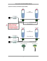
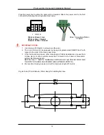
On Pro-Guard systems there is an interconnection between the receiver and transmitter.
Connect the Interconnection Line Plug onto socket J3 (6-pin connector) on the PC Board as
shown in the picture below (both transmitter and receiver, circled in red).
Pro-Guard Receiver – Bottom PCB
Pro-Guard Transmitter – Bottom PCB
Note: If this is a Pro-Guard installation using two Transmitters & one Receiver, use J3
and J12 to connect the two transmitters. Do not use the J1 (Rx Slave) port.
6-Pin Interconnection
Connector
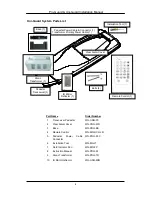
Screw Torque
Specifications
1.7Kg/cm
Summary of Contents for Pro-Guard
Page 4: ......