Installation, Use & Care Manual
This manual is updated as new information and models are released.
Visit our website for the latest manual. www.manitowocice.com
America’s #1 Selling Ice Machine
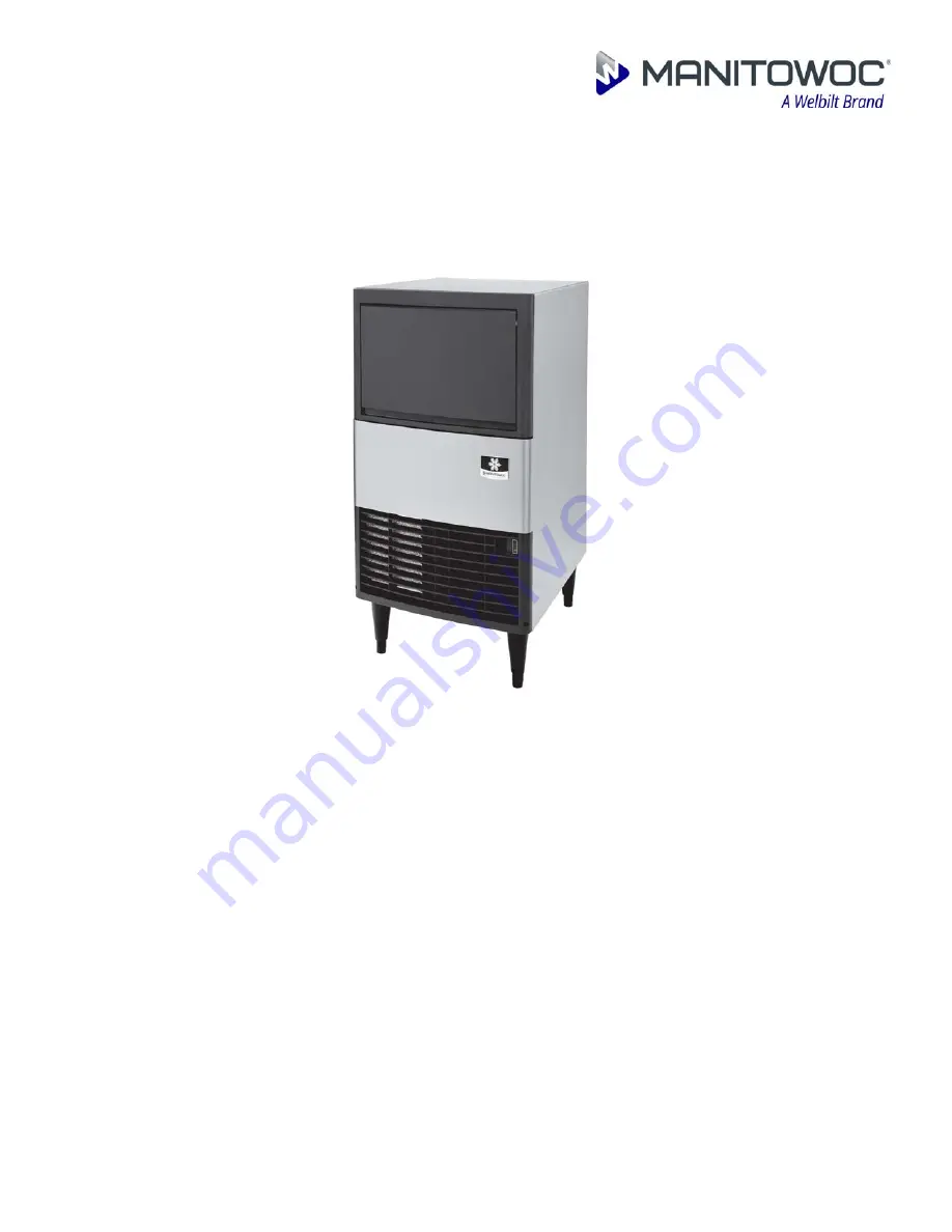
U65
UnderCounter Model
Part Number 040006019 07/18
Page 1: ...re Manual This manual is updated as new information and models are released Visit our website for the latest manual www manitowocice com America s 1 Selling Ice Machine U65 UnderCounter Model Part Num...
Page 2: ......
Page 3: ...t in death or serious injury Caution Indicates a hazardous situation that if not avoided could result in minor of moderate injury DANGER Notice Indicates information considered important but not hazar...
Page 4: ...ield must be worn DANGER Follow these precautions to prevent personal injury during use and maintenance of this equipment It is the responsibility of the equipment owner to perform a Protective Equipm...
Page 5: ...Heat of Rejection 2 2 Leveling the Ice Machine 2 2 Electrical Service 2 3 VOLTAGE 2 3 FUSE CIRCUIT BREAKER 2 3 ELECTRICAL RATING 2 3 ELECTRICAL CORD STRAIN RELIEF 2 4 TERMINAL BLOCK WIRE CONNECTION 2...
Page 6: ...4 Maintenance Interior Cleaning and Sanitizing 4 1 GENERAL 4 1 CLEANING AND SANITIZING PROCEDURE 4 1 Exterior Cleaning 4 3 Ice Machine Inspection 4 3 Cleaning The Condenser 4 4 Removal from Service Wi...
Page 7: ...en requesting information from your Welbilt distributor service representative or the factory The model and serial number are listed on the OWNER WARRANTY REGISTRATION CARD They are also listed on the...
Page 8: ...elbilt Inc 3 Damage caused by improper installation of the ice machine electrical supply water supply or drainage or damage caused by floods storms or other acts of God 4 Premium labor rates due to ho...
Page 9: ...d warranty does not cover and you are solely responsible for the costs of 1 periodic or routine maintenance 2 repair or replacement of the Product or parts due to normal wear and tear 3 defects or dam...
Page 10: ...General Information Section 1 1 4 Part Number 040006019 07 18 THIS PAGE INTENTIONALLY LEFT BLANK...
Page 11: ...Part Number 040006019 07 18 2 1 Section 2 Installation Instructions General These instructions are provided to assist the qualified installer Dimensions 50 00cm 79 00cm 57 00cm...
Page 12: ...n B T U Hour Because the heat of rejection varies during the ice making cycle the figure shown is an average Ice machines like other refrigeration equipment reject heat through the condenser It is hel...
Page 13: ...G The electrical rating is used to help select the wire size of the electrical supply The wire size or gauge also depends on location materials used length of run etc so it must be determined by a qua...
Page 14: ...t onto the cord holder TERMINAL BLOCK WIRE CONNECTION After the electrical cord is installed in the strain relief device the cord must be connected to the terminal block to supply power to the ice mac...
Page 15: ...to accommodate drainage from all drains Insulate the bin drain line to prevent condensation WATER SUPPLY AND DRAIN LINE SIZING CONNECTIONS 1 Min Minimum 2 Max Maximum 3 A 3 4 by 11 1 2 threads per inc...
Page 16: ...Number 040006019 07 18 Typical Water Supply and Drain Line Sizing and Connections ICE MAKING WATER INLET TUBING 0 95 cm 3 8 MINIMUM INSIDE DIAMETER ICE MAKING BIN WATER DRAIN TUBING 1 59 cm 5 8 MINIM...
Page 17: ...gizes to purge the water in the water trough The hot gas valve also energizes at the beginning of the harvest cycle to divert hot refrigerant gas into the evaporator The hot refrigerant gas warms the...
Page 18: ...200 270g 7 9 oz If the slab weight is within this range the ice machine is working properly and no further action is needed If the slab weight is not within this range or you desire a slightly thicker...
Page 19: ...ete approximately 45 minutes then place the toggle switch in the OFF position disconnect power and water supplies to the ice machine step 6 Remove parts for cleaning A Remove the Overflow Tube To remo...
Page 20: ...bottom sides and top Rinse all areas thoroughly with clean water step 10 Mix a solution of sanitizer and warm water step 11 Use 1 2 of the sanitizer water solution to sanitize all removed components U...
Page 21: ...reas step 21 Replace all removed components step 22 Reapply power and water to the ice machine and place the toggle switch in the ICE position Exterior Cleaning Clean the area around the ice machine a...
Page 22: ...he fan blades and motor with a soft cloth Do not bend the fan blades If the fan blades are excessively dirty wash with warm soapy water and rinse thoroughly Removal from Service Winterization Special...
Page 23: ...t 10 C 50 F Ice machine does not release ice or is slow to harvest Ice machine is dirty Clean and sanitize the ice machine Ice machine is not level Level the ice machine Low air temperature around ice...
Page 24: ...upply Ice thickness adjustment dial is not set properly Adjust the ice thickness adjustment dial Incorrect incoming water pressure Water pressure must be 240 620 kPA 34 8 89 9 psi Ice machine is not l...
Page 25: ......
Page 26: ...outh 26th Street Manitowoc WI 54220 Ph 844 724 2273 Visit us online at WWW MANITOWOCICE COM 2010 Welbilt Continuing product improvements may necessitate change of specifications without notice Part Nu...