


8.3 Attaching markers
1
1
2
3
4
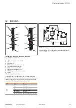
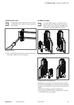
Installing an end bracket
1
WAD 8 group marker or EM 8/30 end bracket marker
2
WS terminal marker for 6 mm pitch (WS 10/6 or WS 8/6)
3
WS terminal marker for 6 mm pitch (WS 10/6 or WS 8/6)
4
WAD 5 group marker
We recommend fitting the thumbwheel switch of
adjustable load monitors with a terminal marker
displaying the adjusted value.
Fitting a marker on an end bracket
The WEW 35/2 end brackets can only be fitted
with a marker if they are not installed together
with an end plate.
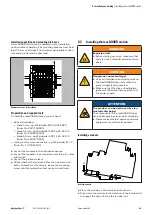
8.4 Installing cross-connectors
WARNING
Explosion risk!
▶
Before starting any work, make sure that
there is not a potentially explosive atmos-
phere!
▶
For applications in explosive risk zones,
observe the installation and construction
requirements of EN 60079-15 and/or
country-specific regulations.
WARNING
Dangerous contact voltage!
▶
Carry out installation and wiring work on
the maxGUARD station only when the
power supply is disconnected.
▶
Make sure that the place of installation
(panel etc.) has been disconnected from
the power supply!
ATTENTION
Risk of short circuit due to non-insulated cross-
connectors!
▶
Insert an AMG PP separation plate wherever there are
bare cut edges next to one another.
ATTENTION
Risk of malfunction!
▶
Do not connect multiple load monitors in parallel or in
series.
▶
Never connect the signal contacts of the control and
alarm modules to the outputs of the load monitors.
ATTENTION
The product can be destroyed!
If the total current is over 20 A, all main strands must each
be equipped with two cross-connectors.
Once the maxGUARD station has been mechanically in-
stalled, the cross-connectors can be fitted in accordance with
the installation drawing or wiring diagram.
50
Manual maxGUARD
2526740000/02/03.2018
8 Installation and wiring
| Attaching markers


