


32
Manual maxGUARD
2526740000/02/03.2018
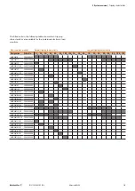
5 Feed-in modules, control modules, alarm modules
| Control modules AMG CM...
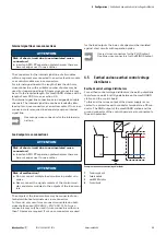
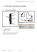
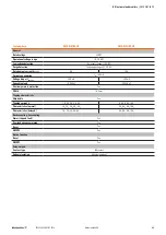
5.3 Control modules AMG CM...
AMG CM...
1
+24 V main strand connection (+24 V)
2
PWR LED
3
ON/OFF LED
4
Reset key
5
I>90% connection (2.5 mm
2
)
6
ON/OFF connection (2.5 mm
2
)
7
GND main strand connection (0 V)
8
Reset connection (2.5 mm
2
)
9
Alarm connection (2.5 mm
2
)
10
Markers
11
Internal signal line connection
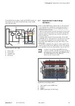
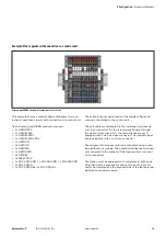
The AMG ELM electronic load monitors can be controlled
and monitored using control modules. Control modules drive
the internal bus and connect the internal signal line to an ex-
ternal control unit. A control module and the connected load
monitors form a unit concerning the control.
LED
Colour
Meaning
PWR
Green
Fault-free operation
Red, flashing
Supply voltage error
Red
Alarm tripped or
internal fault
ON
Yellow
Reset tripped or
ON/OFF tripped
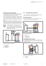
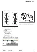
AMG CM... block diagram
Signal
Function
Type
Level
Reset
Resets electronic load monitors
Input
LOW: no reset
HIGH: reset
ON/OFF
Switches load monitors on/off
Input
LOW: ON
HIGH: OFF
Alarm
Load monitor tripped
Output
LOW: alarm
HIGH: no alarm
I>90%
Overload advance warning
Output
LOW: I < 90% I
T
HIGH: I > 90% I
T
The reference point for the signals is the potential of the
GND main strand.
The reset key “R” can be used to manually reset and switch
on/off the connected load monitors.
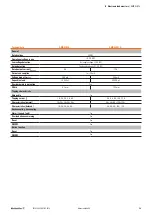
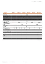
Technical data
AMG CM...
General
Rated voltage
24 V DC
Operational voltage range
18 – 30 V DC
Low voltage detection
Yes (supply voltage < 18 V DC)
Surge detection
Yes (supply voltage > 31.2 V DC)
Operating current consumption
(typical)
100 mA
Width
12.2 mm
Digital inputs
Input resistance
10 kΩ
Input voltage hysteresis
LOW➝HIGH: 15 V
HIGH➝LOW: 5 V
Digital outputs
Active transistor output
24 V/ 20 mA
Short-circuit-proof
Yes


