


31
Manual maxGUARD
2526740000/02/03.2018
5 Feed-in modules, control modules, alarm modules
| Active feed-in modules AMG FIM-C...
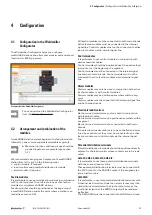
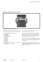
5.2 Active feed-in modules AMG FIM-C...
AMG FIM-C...
1
+24 V main strand connection (+24 V)
2
+24 V feed-in connection (16 mm
2
)
3
GND feed-in connection (16 mm
2
)
4
PWR LED (green/red)
5
Alarm LED (red)
6
Reset LED (yellow)
7
GND main strand connection (0 V)
8
Reset connection (1.5 mm
2
)
9
Alarm connection (1.5 mm
2
)
10
Marker
11
Internal signal line connection
Feed-in modules are used to connect the feed-in conductors.
They connect the power supply to the main strands of the
maxGUARD station. The AMG ELM electronic load moni-
tors can be controlled and monitored using active feed-in
modules. Active feed-in modules drive the internal bus and
connect the internal signal line to an external control unit. An
active feed-in module and the connected load monitors form
unit concerning the control.
LED
Colour
Meaning
PWR
Green
Fault-free operation
Red, flashing (5 Hz)
Supply voltage error
Alarm
Red
Alarm tripped
Reset
Yellow
Reset tripped
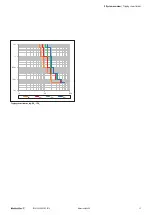
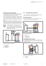
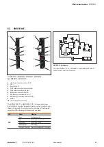
AMG FIM-C... block diagram
Signal
Function
Type
Level
Reset
Resets electronic load monitors
Input
LOW: no reset
HIGH: reset
Alarm
Load monitor tripped
Output
LOW: alarm
HIGH: no alarm
The reference point for the signals is the potential of the
GND main strand.
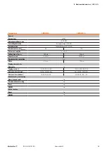
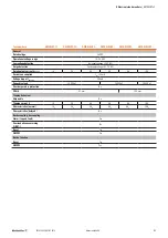
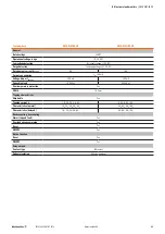
Technical data
AMG FIM-C...
General
Rated voltage
24 V DC
Operational voltage range
18 – 30 V DC
Low voltage detection
Yes (supply voltage < 18 V DC)
Surge detection
Yes (supply voltage > 31.2 V DC)
Operating current consumption
(typical)
100 mA
Width
12.2 mm
Digital inputs
Input resistance
10 kΩ
Input voltage hysteresis
LOW➝HIGH: 15 V
HIGH➝LOW: 5 V
Digital outputs
Active transistor output
24 V/ 20 mA
Short-circuit-proof
Yes


