


25
Manual maxGUARD
2526740000/02/03.2018
4 Configuration
| Segmentation of control voltage distributors
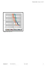
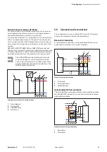
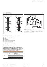
The potential-free coupling of reset and ON/OFF signals can
be achieved, for example, using Weidmüller relay modules
and solid-state relays.
2
3
+24 V
Reset
ON/OFF
Alarm
I>90%
4
0 V
1
+24 V
GND
OUT
OUT
0 V
Example of potential-free signal coupling
1
Feed-in module
2
Control module
3
maxGUARD station
4
Control board
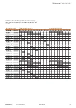
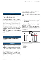
4.7 Segmentation of control voltage
distributors
Within a maxGUARD station, load groups can be combined
to form individually controlled and monitored segments. A
segment always consists of a control module and at least
one electronic load monitor.
A separate internal signal line must be provided for each seg-
ment, and may not be connected to the internal signal lines
of other segments. A segment may contain a maximum of
25 bus participants.
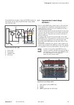
A feed-in module connects the power supply to the entire
maxGUARD station. All segments are connected to a shared
plus potential and a shared minus potential via the main
strands (for maxGUARD stations longer than 300 mm, see
The reference potential for the control module signals is the
shared minus potential of the GND main strand. This applies
to non-earthed as well as earthed systems (see section 4.5).
In order to arrange the maxGUARD station as
clearly as possible, individual segments should be
separated from one another with AMG PP separa
-
tion plates. Markers on the separation
plates can also improve clarity.
1
2
3
4
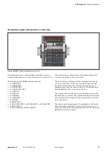
Segmentation of a control voltage distributor
1
Feed-in module for entire maxGUARD station
2
Segment 1
3
Segment 2
4
AMG PP separation plate with WAD 5 marker


