


11
Vector Control
11-14 | CFW700
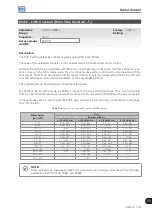
11.7.1 Adjustment of the Parameters P0409 to P0412 Based on the Motor Data Sheet
Being in the possession of the motor equivalent circuit data, it is possible to calculate the value to be programmed
in the parameters from P0409 to P0412, instead of using the self-tuning to obtain them.
Input data:
Motor data sheet:
V
n
= testing voltage to get the motor parameters in Volts.
f
n
= testing frequency to get the motor parameters in Hz.
R
1
= resistance of the motor stator per phase, in Ohms.
R
2
= resistance of the motor rotor per phase, in Ohms.
X
1
= stator inductive reactance, in Ohms.
X
2
= rotor inductive reactance, in Ohms.
X
m
= magnetizing inductive reactance, in Ohms.
I
o
= motor no load current.
ω
= angular speed.
ω
=2 x π x f
n
P0409 =
P0400 x R
1
V
n
P0410 =
V
n
x I
o
x 0.95
P0400
P0411 =
P0400 x [X
1
+(X
2
x X
m
)/(X
2
+ X
m
)]
V
n
x
ω
P0412 =
P0400 x (X
m
+ X
2
)
V
n
x
ω
x R
2
11.8 VECTOR CONTROL
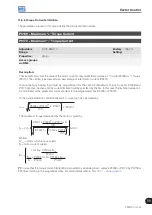
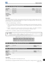
11.8.1 Speed Regulator
The parameters related to the CFW700 speed regulator are presented in this group.
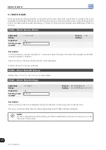
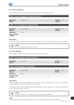
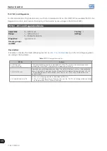
P0160 – Speed Regulation Optimization
Adjustable
Range:
0 = Normal
1 = Saturated
Factory
Setting:
0
Properties:
cfg and Vector
Access groups
via HMI:
Description:
Set P0160=1 (Saturated) for torque control in vector mode with encoder. For more details, refer to the
, in this manual.
Summary of Contents for CFW700
Page 2: ......
Page 4: ......
Page 8: ...Summary...
Page 34: ...2 General Information 2 4 CFW700...
Page 38: ...3 About the CFW700 3 4 CFW700...
Page 56: ...7 Starting up and Settings 7 4 CFW700...
Page 58: ...8 Available Control Types 8 2 CFW700...
Page 78: ...10 VVW Control 10 8 CFW700...
Page 158: ...13 Digital and Analog Inputs and Outputs 13 28 CFW700...


