background image

10

VVW Control

10-2 | CFW700

P

02

02

=

3 (

V

V

W

 C

on

tr

ol

)

U

d

P

01

51

U

d

D

C V

ol

ta

ge 

R

eg

ul

at

io

n

H

ol

d

P

01

00

-P

01

04

t

Fi

lte

r

+

+

R

ef

er

en

ce

(R

ef

er t

Fi

gu

re 1

3.

8

)

P

01

34

P

01

33

P

04

03

f

sl

ip

F

sl

ip 

C

al

cu

la

tio

f

o

T

L

/T

R

, s

R

f

o

l

a

l

o

m

To

rq

ue 

E

st

im

at

io

P

04

04

, P

03

99

,

P

04

01

, P

04

09

P

04

02

, P

04

03

U

d

l

o

l

C

al

cu

la

tio

I

v

 , I

w

P

02

95

l

a

I

v

 , I

w

l

C

al

cu

la

tio

n

m

P

02

95

f

o

m

P

W

M

I

v

 , I

w

S

pa

ce V

ec

to

M

od

ul

at

io

n   

P

W

M

S

pe

ed 

D

ire

ct

io

n

f

o

l

a

l

o

Fl

ux C

on

tr

ol

m

*

U

d

Li

ne

O

ut

pu

t V

ol

ta

ge 

C

om

pe

ns

at

io

n

U

d

P

04

00

, P

04

03

P

04

01

, P

04

07

P

04

09

, P

01

78

l

o

M I

P

01

51

t

Figure 10.1:

 VVW control block diagram 

Summary of Contents for CFW700

Page 1: ...Motors Automation Energy Transmission Distribution Coatings Frequency Inverter CFW700 Programming and Troubleshooting Manual...

Page 2: ......

Page 3: ...Programming and Troubleshooting Manual Series CFW700 Language English Document Number 10001006882 00 Software Version 1 0X Publication Date 06 2011...

Page 4: ......

Page 5: ...NS 5 1 5 1 PARAMETERS STRUCTURE 5 1 5 2 GROUPS ACCESSED IN THE OPTION MENU IN THE MONITORING MODE 5 1 5 3 PASSWORD SETTING IN P0000 5 2 5 4 HMI 5 3 5 5 DISPLAY INDICATIONS IN THE MONITORING MODE SETTI...

Page 6: ...DER 11 28 12 FUNCTIONS COMMON TO ALL THE CONTROL MODES 12 1 12 1 RAMPS 12 1 12 2 SPEED REFERENCES 12 3 12 3 SPEED LIMITS 12 5 12 4 ZERO SPEED LOGIC 12 7 12 5 FLYING START RIDE THROUGH 12 8 12 5 1 V f...

Page 7: ...e Transducer 19 8 19 2 6 Academic PID 19 8 19 2 7 Parameters 19 9 19 3 ELECTRONIC POTENTIOMETER APPLICATION EP 19 16 19 3 1 Description and Definitions 19 16 19 3 2 Operation 19 17 19 3 3 Parameters 1...

Page 8: ...Summary...

Page 9: ...0 DO1 Bit 1 DO2 Bit 2 DO3 Bit 3 DO4 Bit 4 DO5 ro I O or READ 13 14 16 4 P0014 AO1 Value 0 00 to 100 00 ro I O or READ 13 5 16 4 P0015 AO2 Value 0 00 to 100 00 ro I O or READ 13 5 16 4 P0018 AI1 Value...

Page 10: ...Fault DIx Status Bit 0 DI1 Bit 1 DI2 Bit 2 DI3 Bit 3 DI4 Bit 4 DI5 Bit 5 DI6 Bit 6 DI7 Bit 7 DI8 ro READ 16 10 P0097 Last Fault DOx Status Bit 0 DO1 Bit 1 DO2 Bit 2 DO3 Bit 3 DO4 Bit 4 DO5 ro READ 16...

Page 11: ...ass 35 7 Class 40 8 Class 45 1 Class 10 cfg 15 5 P0160 Speed Regulation Optimization 0 Normal 1 Saturated 0 Normal cfg and Vector 11 14 P0161 Speed Proportional Gain 0 0 to 63 9 7 4 Vector 11 15 P0162...

Page 12: ...eter Selection 0 to 1199 1 HMI 5 3 P0207 Bar Graph Parameter Selection 0 to 1199 3 HMI 5 3 P0208 Main Display Scale Factor 0 1 to 1000 0 100 0 HMI 5 4 P0209 Engineering Unit 0 None 1 V 2 A 3 rpm 4 s 5...

Page 13: ...3 FR Key REV 4 DIx 5 Serial FWD 6 Serial REV 7 CO DN DP H 8 CO DN DP AH 9 SoftPLC H 10 SoftPLC AH 11 AI2 Polarity 2 FR Key FWD cfg I O 13 23 19 29 P0224 LOC Run Stop Selection 0 I O Keys 1 DIx 2 Seri...

Page 14: ...P0237 AI2 Gain 0 000 to 9 999 1 000 I O 13 3 P0238 AI2 Signal Type 0 0 to 10 V 20 mA 1 4 to 20 mA 2 10 V 20 mA to 0 3 20 to 4 mA 4 10 V to 10 V 0 0 to 10 V 20 mA cfg I O 13 5 19 9 P0239 AI2 Offset 10...

Page 15: ...ication Function 3 23 Application Function 4 24 Application Function 5 25 Application Function 6 26 Application Function 7 27 Application Function 8 1 Run Stop cfg I O 13 9 19 10 19 18 19 26 19 30 P02...

Page 16: ...9 Application Function 6 40 Application Function 7 41 Application Function 8 13 No Fault cfg I O 13 14 19 10 P0276 DO2 Function Refer to the P0275 options 2 N Nx cfg I O 13 14 19 10 P0277 DO3 Function...

Page 17: ...hing Frequency 0 1 25 kHz 1 2 5 kHz 2 5 0 kHz 3 10 0 kHz 2 5 0 kHz cfg 6 5 P0298 Application 0 Normal Duty ND 1 Heavy Duty HD 0 Normal Duty ND cfg 6 6 P0299 Starting DC Braking Time 0 0 to 15 0 s 0 0...

Page 18: ...hrough I Gain 0 000 to 9 999 0 128 Vector 12 16 P0327 FS I f Current Ramp 0 000 to 1 000 s 0 070 Sless 12 10 P0328 Flying Start Filter 0 000 to 1 000 s 0 085 Sless 12 10 P0329 FS I f Frequency Ramp 2...

Page 19: ...1 11 P0403 Motor Rated Frequency 0 to 300 Hz 60 50 Hz cfg MOTOR 10 4 11 11 P0404 Motor Rated Power 0 0 33 HP 0 25 kW 1 0 5 HP 0 37 kW 2 0 75 HP 0 55 kW 3 1 HP 0 75 kW 4 1 5 HP 1 1 kW 5 2 HP 1 5 kW 6 3...

Page 20: ...83 Serial Speed Reference 32768 to 32767 ro NET 17 1 P0684 CO DN DP Control Word Refer to the P0682 options ro NET 17 1 P0685 CO DN DP Speed Reference 32768 to 32767 ro NET 17 1 P0695 Settings for the...

Page 21: ...3 Error Control Enabled 4 Guarding Error 5 Heartbeat Error ro NET 17 2 P0722 CANopen Node Status 0 Disabled 1 Initialization 2 Stopped 3 Operational 4 Preoperational ro NET 17 2 P0740 Profibus Communi...

Page 22: ...l Word 1 0000h to FFFFh 0000h ro NET 17 3 P0968 Status Word 1 0000h to FFFFh 0000h ro NET 17 3 P1000 SoftPLC Status 0 No Applicative 1 Installing App 2 Incompatible App 3 Stopped Applicative 4 Applica...

Page 23: ...18 2 19 15 P1032 SoftPLC Parameter 23 32768 to 32767 0 cfg SPLC 18 2 19 15 P1033 SoftPLC Parameter 24 32768 to 32767 0 cfg SPLC 18 2 P1034 SoftPLC Parameter 25 32768 to 32767 0 cfg SPLC 18 2 P1035 So...

Page 24: ...059 SoftPLC Parameter 50 32768 to 32767 0 cfg SPLC 18 2 Notes ro Read only parameter rw Reading writing parameter cfg Configuration parameter it can be changed only with stopped motor V f Parameter av...

Page 25: ...can be disabled by setting P0350 0 or 2 The inverter output current is too high F048 IGBT Overload Fault It is the IGBT overload fault The inverter output current is too high A050 IGBT High Temperatu...

Page 26: ...rounding air temperature Not installed motor thermistors Blocked motor shaft A128 Serial Communication Timeout It indicates that the inverter stopped receiving valid telegrams during a certain period...

Page 27: ...y Stop Relays Safety stop relay fault One of the relays is defective or it does not have 24 V applied to its coil A163 AI1 Broken Cable It indicates that the AI1 current 4 20 mA or 20 4 mA reference i...

Page 28: ...information F240 2 Profibus DP Module Access Error It indicates an error in the access to the Profibus DP communication module data Verify whether the Profibus DP module is correctly fit into the slo...

Page 29: ...g have the purpose of protecting the user against dead serious injuries and considerable material damage ATTENTION The procedures recommended in this warning have the purpose of avoiding material dama...

Page 30: ...nect the input power before touching any electrical component associated to the inverter Many components can remain charged with high voltages or remain in movement fans even after that AC power is di...

Page 31: ...deceleration Inom HD Inverter rated current for use with heavy overload regimen HD Heavy Duty Overload 1 5 x Inom HD 1 minute Rectifier The input circuit of the inverters that converts the input AC vo...

Page 32: ...ching the speed reference and when deactivated Stop decelerates the motor with the deceleration ramp down to stop It can be commanded through digital input programmed for that function or via serial T...

Page 33: ...ith a stopped motor V f Parameter visible on the keypad HMI only in the V f mode P0202 0 1 or 2 Adj Parameter visible on the keypad HMI only in the V f adjustable mode P0202 2 Vector Parameter visible...

Page 34: ...2 General Information 2 4 CFW700...

Page 35: ...vector control can be programmed as sensorless which means that standard motors without the need of encoder or vector control with motor encoder The sensorless vector control allows high torque and f...

Page 36: ...Motor Inverter with IGBT transistors Power Supply DC link connection Dynamic braking resistor connection Pre charge WPS software WLP software Capacitor Bank RFI filter HMI CC700 Control Board with 32...

Page 37: ...ol accessory module refer to section 7 2 Accessories of the CFW700 user s manual 5 FLASH memory module not included 6 Front cover sizes A B and C 7 Keypad HMI 8 Status LED STATUS 9 CC700 control board...

Page 38: ...3 About the CFW700 3 4 CFW700...

Page 39: ...1 in LOC and or P0228 1 in REM Press this key to decelerate the motor according to the deceleration ramp time This option is active when P0224 0 in LOC and or P0227 0 in REM Press this key to acceler...

Page 40: ...4 Keypad HMI 4 2 CFW700 Figure 4 2 Back of the keypad HMI Installation The keypad HMI can be installed or removed with the inverter energized...

Page 41: ...tion some parameters present values in parentheses which must be adjusted in the inverter for using the 50 Hz frequency 5 2 GROUPS ACCESSED IN THE OPTION MENU IN THE MONITORING MODE In the monitoring...

Page 42: ...esult Display Indication 1 Monitoring mode Press the ENTER MENU key to enter into the 1 level of the programming mode 2 The PARAM group is already available press the ENTER MENU key to access paramete...

Page 43: ...t of P0000 is equal to the password 2 Change Password It makes the value presented in P0000 the current password Follow the procedure below to change your password 1 Enter the current password value f...

Page 44: ...play and the Secondary Display in order to convert motor variables such as speed rpm in production units such as meters minutes or cubic feet minutes for example P0209 Main Display Engineering Unit Ad...

Page 45: ...g the parameters of the inverter the display is designed to show three parameters at the same time according to the user s choice Two of these parameters Main Display and Secondary Display are shown i...

Page 46: ...Programming Off 8 Two or more DIx P0263 P0270 programmed for 27 Load User 1 9 Two or more DIx P0263 P0270 programmed for 28 Load User 2 10 P0202 programmed for 0 V f 60 Hz OR 1 V f 50 Hz OR 2 Adjustab...

Page 47: ...er Current specifications for operation with normal overload cycle ND Current specifications for operation with heavy overload cycle HD a Nameplate affixed to the side of the inverter CFW700 model Par...

Page 48: ...troller FLASH memory CC CAN RS 485 01 CAN and RS 485 interface module CA CAN 01 CAN interface module CD MMF 01 FLASH Memory Module 1 For the FLASH memory module the P0028 identification code will depe...

Page 49: ...ty relay 0 without safety relay 1 with safety relay Bit 8 indicates if the inverter is equipped with RFI suppressor filter 0 without RFI filter 1 with RFI filter Bits 7 and 6 indicate the inverter pow...

Page 50: ...2 A 2 A 1 3 6 A 3 6 A 2 5 A 5 A 3 6 A 5 A 4 7 A 5 5 A 5 7 A 7 A 6 10 A 8 A 7 10 A 10 A 8 13 A 11 A 9 13 5 A 11 A 10 16 A 13 A 11 17 A 13 5 A 12 24 A 19 A 13 24 A 20 A 14 28 A 24 A 15 31 A 25 A 16 33 5...

Page 51: ...table Range 0 1 25 kHz 1 2 5 kHz 2 5 0 kHz 3 10 0 kHz Factory Setting 2 Properties cfg Access groups via HMI Description Refer to the allowed current for switching frequencies different from the defau...

Page 52: ...hat application to high torques in relation to their rated torque when operating in permanent regimen during start acceleration or deceleration The Heavy Duty Regimen HD defines the maximum current fo...

Page 53: ...er 1 10 Save User 2 Factory Setting 0 Properties cfg Access groups via HMI Description It makes it possible to save the actual inverter parameters in an area of the control module memory or the other...

Page 54: ...Range 0 Off 1 VFD MMF 2 MMF VFD 3 VFD Synchronization MMF 4 MMF Format 5 SoftPLC Program Copy Factory Setting 0 Properties cfg Access groups via HMI Description This function allows saving the conten...

Page 55: ...ve an updated copy of the inverter parameters NOTE When the inverter is powered on and the memory module is present the current values of its parameters is overridden if P0318 3 If you want to copy fr...

Page 56: ...7 Starting up and Settings 7 4 CFW700...

Page 57: ...ion VVW Voltage Vector WEG it allows a static speed control more accurate than the V f mode it adjusts itself automatically to the line variations and also to the load variations however it does not p...

Page 58: ...8 Available Control Types 8 2 CFW700...

Page 59: ...urve Refer to the block diagram at the figure 9 1 The advantage of the V f control is that due to its simplicity just a few settings are necessary The start up is fast and simple and the factory setti...

Page 60: ...with the load variation 9 1 V f CONTROL P0136 Manual Torque Boost Adjustable Range 0 to 9 Factory Setting 1 Properties V f Access groups via HMI BASIC Description It acts at low speeds increasing the...

Page 61: ...Factory Setting 0 0 Properties V f Access groups via HMI Description The parameter P0138 is used in the motor slip compensation function when adjusted to positive values In this case it compensates th...

Page 62: ...speed 2 Measure the motor or equipment speed with a tachometer 3 Apply rated load to the equipment 4 Increase the content of P0138 until the speed reaches the value measured before with no load P0139...

Page 63: ...ated frequency 60 Hz P0202 1 for motors with rated frequency 50 Hz Notes The correct setting of P0400 assures the application of the correct V f ratio at the output in case of 50 Hz or 60 Hz motors wi...

Page 64: ...l applications such as for instance when a transformer is used at the inverter output between it and the motor The function is activated with P0202 2 Adjustable V f The factory setting of P0144 8 0 is...

Page 65: ...OFF Current limitation of the Ramp Hold type Inactive fast current limitation Current limitation according to the figure 9 8 a 3 Decel FL OFF Current limitation of the Ramp Deceleration type Inactive...

Page 66: ...n via ramp P0100 Deceleration via ramp P0101 During acceleration During deceleration Time Time Time Time Motor current a Ramp Hold Motor current P0135 Time Time Time Decelerates via ramp P0101 Speed b...

Page 67: ...function to limit the DC link voltage 1 Ramp Hold It is effective only during the deceleration Working When the DC link voltage reaches the level adjusted in P0151 a command is sent to the ramp block...

Page 68: ...in P0151 the difference between these signals is multiplied by the proportional gain P0152 and the result is added to the ramp output Refer to the figures 9 11 and 9 12 In a similar manner as the Ram...

Page 69: ...vel Adjustable Range 339 to 400 V 585 to 800 V 585 to 800 V 585 to 800 V 585 to 800 V Factory Setting 400 V P0296 0 800 V P0296 1 800 V P0296 2 800 V P0296 3 800 V P0296 4 Properties V f and VVW Acces...

Page 70: ...inverter Sequence for installation verification powering and start up 1 Install the inverter according to the chapter 3 Installation and Connection of the CFW700 user s manual wiring all the power an...

Page 71: ...e in permanent regimen Comparing to the Sensorless Vector the settings are simpler and easier The VVW control uses the stator current measurement the stator resistance value that can be obtained with...

Page 72: ...on f o T L T R s R f o l a l o m Torque Estimation P0404 P0399 P0401 P0409 P0402 P0403 U d l o l o Calculation I v I w P0295 l a I v I w l a Calculation m P0295 f o m PWM I v I w Space Vector Modulati...

Page 73: ...e parameters for the used motor data setting are listed in this group They must be adjusted according to the motor nameplate data P0398 to P0406 except P0405 and by means of the Self Tuning or from da...

Page 74: ...It is the motor power factor setting according to the motor nameplate data cos This parameter is important for the VVW control operation The inaccurate setting will imply in incorrect calculation of t...

Page 75: ...2 In this way one gets a stable operation of the control circuit with adequate values to obtain the best motor performance During the Oriented Start up routine the Config Configuration status will be...

Page 76: ...on 10 Set parameter P0202 Type of Control pressing ENTER MENU Press the key to select the desired option 3 VVW Then press ENTER MENU There are three options to exit the oriented start up 1 Running the...

Page 77: ...option to perform Self tunning The Self tunning should be performed whenever it is possible Press ENTER MENU key to access parameter P0408 and press to select the option 1 No rotation Refer to item 11...

Page 78: ...10 VVW Control 10 8 CFW700...

Page 79: ...d automatically through self tuning or from the motor data sheet supplied by the manufacturer The figure 11 2 presents the block diagram for the vector control with encoder and the figure 11 1 for the...

Page 80: ...t P0185 Default Value P0185 Default Value M I Torque Current PWM Us q I d I q Current Regulator I q I d I q I q I d I d P0179 Gp P0175 Gi P0176 Gp P0186 Gi P0187 Us q Us d U d P0190 P0165 P0185 Gd P01...

Page 81: ...usly described with the following additional benefits Torque and speed control down to 0 zero rpm Speed control accuracy of 0 01 if digital references are used for instance via keypad HMI Profibus DP...

Page 82: ...P0161 Gi P0162 Gp P0167 Gi P0168 Us d Flux Current MI 3 Torque Current PWM Vca Us q Current Regulator I q I d I q I q I d I d P0179 Gp P0175 Gi P0176 Gd P0166 Gp 1 00 Gi 0 00 DIx 15 Speed Torque R T O...

Page 83: ...e motor parameters that are not available on the motor nameplate necessary for the operation of the sensorless vector or vector with encoder control are estimated Stator resistance Motor flux leakage...

Page 84: ...ugh P0413 be all different from zero For more details on the self tuning parameters refer to item 11 8 5 Self Tuning in this manual Alternatives for the acquisition of the motor parameters Instead of...

Page 85: ...torque current limitation is adjusted in P0170 The torque at the motor shaft Tmotor in is given by the formula The equation below must be used for torque Replace P0169 by P0170 for torque P0401 x P01...

Page 86: ...ncrease of the temperature Verify the impact of those effects in the application before using the optimal braking It is a function that helps the motor controlled braking eliminating in many cases the...

Page 87: ...5 kW IV poles 0 76 resulting in TB1 0 32 20 hp 15 0 kW IV poles 0 86 resulting in TB1 0 16 T Tnom N Nnom TB1 1 0 0 0 0 2 1 0 2 0 c b a a Torque generated by the motor in normal operation driven by the...

Page 88: ...a reserve of power that gives the motor the capability to withstand working in adverse conditions Set it according to the value informed on the motor nameplate It affects the motor overload protection...

Page 89: ...e 11 2 P0402 Motor Rated Speed Adjustable Range 0 to 18000 rpm Factory Setting 1750 rpm 1458 rpm Properties cfg Access groups via HMI MOTOR Description Set it according to the used motor nameplate dat...

Page 90: ...5 3 1 0 4 1 5 5 2 0 6 3 0 7 4 0 8 5 0 9 5 5 10 6 0 11 7 5 12 10 0 13 12 5 14 15 0 15 20 0 16 25 0 17 30 0 18 40 0 19 50 0 20 60 0 21 75 0 22 100 0 23 125 0 24 150 0 25 175 0 NOTE When adjusted via key...

Page 91: ...100 P0157 Overl Curr 50 P0158 Overl Curr 5 0 1 05xP0401 0 9xP0401 0 65xP0401 1 1 05xP0401 1 05xP0401 1 05xP0401 2 1 05xP0401 1 0xP0401 1 0xP0401 ATTENTION Refer to the section 11 4 Optimal Flux for S...

Page 92: ...motor rotor per phase in Ohms X1 stator inductive reactance in Ohms X2 rotor inductive reactance in Ohms Xm magnetizing inductive reactance in Ohms Io motor no load current angular speed 2 x x fn P040...

Page 93: ...ization of the Speed Regulator 1 Select the acceleration P0100 and or deceleration P0101 time according to the application 2 Adjust the speed reference for 75 of the maximum value 3 Configure an analo...

Page 94: ...escription It adjusts the speed filter time constant Refer to the figure 13 2 NOTE Generally this parameter must not be changed The increment in its value turns the system response slower P0166 Speed...

Page 95: ...ers related to the CFW700 flux regulator are presented next P0175 Flux Regulator Proportional Gain Adjustable Range 0 0 to 31 9 Factory Setting 2 0 P0176 Flux Regulator Integral Gain Adjustable Range...

Page 96: ...0 95 x P0296 Automatic setting during the Oriented Start up Routine 0 95xP0400 Properties Vector Access groups via HMI Description This parameter defines the value of the maximum output voltage Its s...

Page 97: ...and 15 rpm for 50 Hz rated frequency IV pole motors NOTE For P0182 3 rpm the I f function will be disabled and the inverter will remain always in the sensorless vector mode P0183 Current in the I f Mo...

Page 98: ...coder P0413 P0408 1 No rotation The motor stands still during the self tuning The P0410 value is obtained from a table valid for WEG motors up to 12 poles NOTE Therefore P0410 must be equal to zero be...

Page 99: ...consideration Vector mode with encoder P0202 5 When using P0408 2 Run for Im one must after finishing the self tuning routine couple the load to the motor and set P0408 4 Estimate Tm in order to esti...

Page 100: ...ith a value equal to the motor no load current before initiating the self tuning For P0202 5 vector mode with encoder the value P0410 determines the motor flux therefore it must be properly adjusted I...

Page 101: ...ect the motor will loose torque Thus one must adjust P0412 so that at half the rated speed and with stable load the motor current P0003 stays the lowest possible In the sensorless vector control mode...

Page 102: ...2 it is possible to change them by setting P0413 via keypad HMI The P0161 gain provided by the self tuning or through P0413 change will be limited to the range 6 0 P0161 9 0 The P0162 value varies in...

Page 103: ...P0170 become inactive and the current limitation will be specified by the AIx In this case the limitation value can be monitored at the parameter correspondent to the programmed AIx P0018 or P0019 In...

Page 104: ...g to the next table Table 11 7 DC link regulation modes P0184 Action 0 With losses Optimal Braking The Optimal Braking is active as described at P0185 This assures the minimum possible deceleration ti...

Page 105: ...P0404 20 60 hp the current flux will be increased up to the maximum value defined on P0169 or P0170 as the speed is reduced The break torque in the weakness field area is small 2 Without losses set P0...

Page 106: ...ure 11 5 In this way one gets a stable operation of the control circuit with adequate values to obtain the best motor performance During the Oriented Start up routine the Config Configuration status w...

Page 107: ...ion parameter This change will affect P0156 P0157 P0158 P0401 P0404 and P0410 P0410 only will affect if P0202 0 1 2 or 3 The time and level of the IGBT overload protection will also be affected Press...

Page 108: ...the next parameter 18 If necessary change P0406 Motor Ventilation parameter Press the key to the next parameter 19 In this moment the keypad presents the option to perform Self tuning The Self tuning...

Page 109: ...ate P0100 lineally from 0 to the maximum speed defined in P0134 and decelerate P0101 lineally from the maximum speed down to 0 Note The setting 0 0 s means that the ramp is disabled P0102 Acceleration...

Page 110: ...ramp function refer to item 13 1 3 Digital Inputs for more details Note The setting 0 0 s means that the ramp is disabled P0104 Ramp Adjustable Range 0 Linear 1 S Curve Factory Setting 0 Properties A...

Page 111: ...P0680 Logical status 12 2 SPEED REFERENCES This parameter group makes it possible that the reference values for the motor speed and for the functions JOG JOG and JOG be established It is also possibl...

Page 112: ...on During the JOG command the motor accelerates up to the value defined in P0122 following the adjusted acceleration ramp The source of the JOG command is defined in the parameters P0225 Local Situati...

Page 113: ...10 P0269 11 DI8 P0270 10 P0270 11 During the JOG or JOG commands the values of P0122 and P0123 are respectively added or subtracted from the speed reference to generate the total reference refer to t...

Page 114: ...ASIC Description They define the maximum minimum values for the motor speed reference when the inverter is enabled They are valid for any type of reference signal For details on the actuation of P0133...

Page 115: ...cause of the process conditions In case you want to handle or perform any type of maintenance remove power from the inverter P0218 Condition to Leave the Zero Speed Disable Adjustable Range 0 Referenc...

Page 116: ...then the time counting will be reset and the inverter continues enabled P0291 Zero Speed Zone Refer to item 13 1 4 Digital Outputs Relays for more details 12 5 FLYING START RIDE THROUGH The FLYING STA...

Page 117: ...n which the frequency goes from P0134 to zero After this second scan the FS is finished and the control mode changes to vector sensorless The figure 12 4 c shows the speed reference when the FS functi...

Page 118: ...escription It establishes the time of permanence in the condition that indicates that the speed of the motor was found It is defined by P0328 P0412 8 0 015 s P0329 FS I f Frequency Ramp Adjustable Ran...

Page 119: ...003 1s N N 1s I f I f time time time I 0 9 x P0401 a b c d Figure 12 4 a to d Influence of P0327 and P0329 during Flying Start P0202 4 If it is wished to deactivate momentarily the Flying Start functi...

Page 120: ...put Speed P0002 0 rpm Line Returns P0332 Enabled Disabled P0331 Disabled Output Pulses Time adjusted in P0332 Output Voltage 0 V Output Speed P0002 0 rpm Line Returns Enabled P0332 P0331 F021 Level DC...

Page 121: ...by the reference After the line failure t0 the DC link voltage Ud starts diminishing according to a rate depending on the motor load condition being able to reach the undervoltage level t2 if the Rid...

Page 122: ...If the line voltage produces an Ud voltage between the values adjusted in P0322 and P0323 the fault F150 may occur the values of P0321 P0322 and P0323 must be readjusted NOTE When one of the function...

Page 123: ...ack Adjustable Range 178 to 282 V 308 to 616 V 308 to 616 V 308 to 616 V 308 to 616 V Factory Setting P0296 0 267 V P0296 1 462 V P0296 2 486 V P0296 3 535 V P0296 4 583 V Properties Vector Access gro...

Page 124: ...or Access groups via HMI Description These parameters configure the vector mode Ride Through PI controller which is responsible for keeping the DC link voltage at the level set in P0322 Ud P0325 P0326...

Page 125: ...elated to the DC braking Control Mode DC Braking at Starting DC Braking at Stopping V f scalar P0299 and P0302 P0300 P0301 and P0302 VVW P0302 and P0299 P0300 P0301 and P0302 Sensorless Vector P0299 a...

Page 126: ...iption This parameter sets the DC braking time at stopping The figure 12 9 presents the DC braking operation via ramp disabling refer to P0301 a V f scalar P0300 Motor Speed P0301 DEAD TIME Open Time...

Page 127: ...e motor and it is proportional to its speed During the DC braking the inverter indicates the RUN status at the keypad HMI During the braking process if the inverter is enabled the braking is interrupt...

Page 128: ...P0302 value which varies from 0 to 10 of the rated voltage until getting the desired braking This parameter works only for the V f scalar and VVW control modes P0372 DC Braking Current for Sensorless...

Page 129: ...Setting 900 rpm P0305 Skip Speed 3 Adjustable Range 0 to 18000 rpm Factory Setting 1200 rpm P0306 Skip Band Adjustable Range 0 to 750 rpm Factory Setting 0 rpm Properties Access groups via HMI Descri...

Page 130: ...ter P0192 starts to indicate P0192 Completed P0191 Encoder Zero Search Adjustable Range 0 Inactive 1 Active Factory Setting 0 Properties Access groups via HMI Description On the inverter initializatio...

Page 131: ...ry Setting Properties ro Access groups via HMI READ or I O Description These read only parameters indicate the value of the analog inputs AI1 and AI2 as a percentage of the full scale The indicated va...

Page 132: ...nactive Figure 13 1 b Analog input actuation with Dead Zone Active In case that the analog inputs AI1 and AI2 are programmed for 10 V to 10 V P0233 and P0238 configured in 4 there will be curves ident...

Page 133: ...ed at this parameter will be the maximum torque current expressed as a percentage of the motor rated current P0401 The indication range will be from 0 200 When the analog input is equal to 10 V maximu...

Page 134: ...gram The AIx internal value is the result of the following equation Alx Alx OFFSET x 10 V x Gain 100 For instance AIx 5 V OFFSET 70 and Gain 1 000 Alx 5 70 x 10 V x 1 2 V 100 AIx 2 V means that the mo...

Page 135: ...0 0 to 10 V 0 to 20 mA Off On 1 4 to 20 mA On 2 10 to 0 V 20 to 0 mA Off On 3 20 to 4 mA On 4 10 to 10 V Off When current signals are used at the input the switch corresponding to the desired input m...

Page 136: ...lue 16 Id Current 17 Application Function 1 18 Application Function 2 19 Application Function 3 20 Application Function 4 21 Application Function 5 22 Application Function 6 23 Application Function 7...

Page 137: ...ence Torque Current 0 Motor Torque PTC SoftPLC Gain AO1 P0252 AO2 P0255 Signal AO1 P0253 AO2 P0256 Value AO1 P0014 AO2 P0015 Application Function 1 Application Function 2 Application Function 3 Applic...

Page 138: ...o 20 mA 2 10 V 20 mA to 0 3 20 to 4 mA Factory Setting 0 Properties cfg Access groups via HMI I O Description These parameters configure if the analog output signal will be in current or voltage with...

Page 139: ...al inputs DI1 to DI8 The indication is done by means of the numbers 1 and 0 representing respectively the Active and Inactive states of the inputs The state of each input is considered as one digit in...

Page 140: ...gital Input functions are presented next Run Stop In order to assure the correct operation of this function it is necessary to program P0224 and or P0227 in 1 Local Remote When programmed this functio...

Page 141: ...than P0204 8 with the difference that the user memory is loaded from a transition of the DIx programmed for this function When the state of the DIx changes from low level to high level transition fro...

Page 142: ...cceleration ramp Acceleration ramp Motor speed Open Open 24 V Time Time Motor speed DIx Forward Reverse f FAST STOP d FWD REV c NO EXTERNAL FAULT a RUN STOP b GENERAL ENABLE Motor runs free coasts P01...

Page 143: ...Deceleration ramp 24 V DIx JOG General enable Open Open Aceleration ramp h JOG With Fault 24 V General enable Run Stop Time 24 V Time Time 24 V Without fault Reset DIx Reset Open Motor speed Inverter...

Page 144: ...er it is possible to visualize the status of the control board 5 digital outputs DO1 to DO5 The indication is done by means of the numbers 1 and 0 representing respectively the Active and Inactive sta...

Page 145: ...Application Function 1 35 Application Function 2 36 Application Function 3 37 Application Function 4 38 Application Function 5 39 Application Function 6 40 Application Function 7 41 Application Funct...

Page 146: ...y the F072 fault Motor Overload 4 20 mA OK it means that the current reference 4 to 20 mA at the analog inputs AIx is inside the 4 to 20 mA range P0695 Value it means that the state of the digital out...

Page 147: ...e point of the speed selected by the user Ny P0289 Ny Speed It is a reference point of the speed selected by the user Ix P0290 Ix Current It is a reference point of the current selected by the user Is...

Page 148: ...ransistor ON P0287 P0287 a N Nx N Relay Transistor OFF ON OFF Nx P0288 Time g Is Ix Is Relay Transistor ON OFF ON Ix P0290 Time ON OFF OFF Relay Transistor Motor Torque P0009 Tx P0293 Time h Torque Tx...

Page 149: ...20 mA Reference OK Relay Transistor ON ON OFF Time 2 mA Reference o N Nx and Nt Nx Nt N Relay Transistor OFF ON OFF Time Nx P0288 OFF OFF Enable Hours P0043 6553 h 0 N Relay Transistor ON Hx P0294 Ti...

Page 150: ...tting 4 0 Hz Properties Access groups via HMI Description It is used in the digital output and relay functions F Fx 1 and F Fx 2 P0282 Fx Hysteresis Adjustable Range 0 0 to 15 0 Hz Factory Setting 2 0...

Page 151: ...perties Access groups via HMI Description It is used in the Is Ix and Is Ix functions of the digital and relay outputs P0291 Zero Speed Adjustable Range 0 to 18000 rpm Factory Setting 18 rpm 15 rpm Pr...

Page 152: ...nd relay outputs 13 2 LOCAL AND REMOTE COMMAND In those parameter groups one can configure the origin of the main inverter commands when in the LOCAL or in the REMOTE situation as the Speed Reference...

Page 153: ...fset and its multiplication by the applied gain refer to item 13 1 1 Analog Inputs The value of the reference adjusted with the and is contained in the parameter P0121 P0223 FORWARD REVERSE Selection...

Page 154: ...on P0228 JOG Selection REMOTE Situation Adjustable Range 0 Inactive 1 JOG Key 2 DIx 3 Serial 4 CANopen DeviceNet Profibus DP 5 SoftPLC Factory Setting P0225 1 P0228 2 Properties cfg Access groups via...

Page 155: ...motor in the shortest possible time and will reset the torque current reference NOTE When the control modes V f or VVW are selected the use of the option 2 Fast Stop is not recommended NOTE When the C...

Page 156: ...irection Run Stop JOG Reference Limits P0134 P0133 P0133 P0134 Total Reference Commands and Reference Refer to the figure 13 8 P0122 OFFSET P0163 LOC P0164 REM P0001 P0134 Maximum Reference P0133 Mini...

Page 157: ...RENCE REMOTE REFERENCE LOCAL COMMANDS REMOTE COMMANDS P0220 LOCAL REMOTE Selection REFERENCE COMMANDS COMMANDS REFERENCE FORWARD REVERSE P0223 JOG P0225 RUN STOP P0224 REMOTE REFERENCE P0222 FORWARD R...

Page 158: ...13 Digital and Analog Inputs and Outputs 13 28 CFW700...

Page 159: ...ng resistor has been connected to the CFW700 and if the parameters related to it have been adjusted properly See next the description of the parameters in order to know how to program each one P0153 D...

Page 160: ...curve Steps to enable the dynamic braking Connect the braking resistor Refer to item 3 2 3 2 Dynamic Braking standard built in for sizes A B C and D and optional built in for size E CFW700 DB of the u...

Page 161: ...ch is estimated based on the motor power and number of poles The thermal image is important to allow that a derating in the fault actuation time be given so that shorter actuation times be obtained wh...

Page 162: ...ent for the PTC Therefore it is necessary to configure the DIP switches of the output for current and to set the output function parameter for 11 PTC The analog inputs AI1 and AI2 of the control modul...

Page 163: ...b PTC connection examples 15 3 PROTECTIONS The parameters related to motor and inverter protections are found in this group P0030 IGBTs Temperature P0034 Internal Air Temperature Adjustable Range 20 0...

Page 164: ...urrent P0401 The overload current is given as a function of the speed being applied to the motor according to the overload curve The parameter P0156 P0157 and P0158 are the three points used to form t...

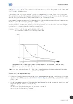
Page 165: ...accordance with UL508C the thermal class should be 20 P0159 3 The necessary data for choosing the thermal class are the following Motor rated current In Blocked rotor current Ip Blocked rotor time TR...

Page 166: ...is it is only necessary to plot the calculated values on the motor overload graph figures 15 3 a or 15 3 b and to select the thermal class curve immediately below the calculated point Class 45 Class 4...

Page 167: ...urrent with the 4 seconds y axis of the Overload Time in the graph of the figure 15 3 b hot motor the thermal class to be selected will be the class 15 t15 P0340 Auto Reset Time Adjustable Range 0 to...

Page 168: ...cription This parameter allows the desired protection level for the motor overload function to be configured Refer to the table below for details on the actuation of each one of the available options...

Page 169: ...rectifiers in case of overload avoiding that damage due to overtemperature at their junctions occurs Thus the parameter P0350 allows configuring the desired protection level for this function even wi...

Page 170: ...d the inverter will be disabled 2 Fault Only the fault F078 will be generated when the motor reaches the overtemperature protection trip level and the inverter will be disabled 3 Alarm Only the alarm...

Page 171: ...IGBTs fault and alarm Internal air fault and alarm 1 IGBTs fault and alarm Internal air fault 2 IGBTs fault Internal air fault and alarm 3 IGBTs fault Internal air fault Factory Setting 0 Properties c...

Page 172: ...rameter P0354 options P0354 Action 0 Inactive The heatsink fan speed fault protection is disabled 1 Fault It enables the fault F179 The inverter will be disabled if the fault occurs P0356 Dead Time Co...

Page 173: ...esents regardless of the origin source the value of the speed reference in rpm factory setting It is also possible to change the speed reference P0121 through this parameter when P0221 or P0222 0 P000...

Page 174: ...ange 0 0 to 1020 0 Hz Factory Setting Properties ro Access groups via HMI READ Description It indicates the inverter output frequency in Hertz Hz P0006 VFD Status Adjustable Range 0 Ready 1 Run 2 Unde...

Page 175: ...lt It indicates that the inverter is in the fault state Self Tuning CONF RUN It indicates that the inverter is executing the self tuning routine Configuration CONF It indicates that the inverter is in...

Page 176: ...put Power Adjustable Range 0 0 to 6553 5 kW Factory Setting Properties ro Access groups via HMI READ Description It shows the inverter instantaneous output power in kilowatt kW NOTE The value indicate...

Page 177: ...Properties ro Access groups via HMI READ Description It indicates the fan actual speed in revolutions per minute rpm P0037 Motor Overload Status Adjustable Range 0 to 100 Factory Setting Properties ro...

Page 178: ...y Setting Properties ro Access groups via HMI READ Description It indicates the total number of hours that the inverter remained powered This value is kept even when power is removed from the inverter...

Page 179: ...when power is removed from the inverter NOTE The value indicated in this parameter is calculated indirectly and must not be used to measure the energy consumption P0045 Enabled Fan Time Adjustable Ra...

Page 180: ...this group are described the parameters that record the last faults occurred in the inverter together with other relevant information for the fault interpretation as current motor speed etc NOTE If th...

Page 181: ...s ro Access groups via HMI READ Description It is the record of the inverter DC link voltage at the moment of the last fault occurrence P0092 Last Fault Speed Adjustable Range 0 to 18000 rpm Factory S...

Page 182: ...es ro Access groups via HMI READ Description It indicates the state of the digital inputs at the moment of the last fault occurrence The indication is done by means of an hexadecimal code which when c...

Page 183: ...ndicate the states active and inactive of the outputs through numbers 1 and 0 Example If the code presented for the parameter P0097 on the keypad HMI is 001C it will correspond to the sequence 0001110...

Page 184: ...16 Read only Parameters 16 12 CFW700...
Page 185: ...te P0311 Serial Interface Byte Configuration P0314 Serial Watchdog P0316 Serial Interface Status P0682 Serial Control Word P0683 Serial Speed Reference Those are parameters for the configuration and o...

Page 186: ...Master Status P0721 CANopen Com Status P0722 CANopen Node Status Those are parameters for the configuration and operation of the CAN interface For a detailed description refer to the CANopen communica...

Page 187: ...ibus Writing 9 P0757 Profibus Writing 10 P0918 Profibus Address P0922 Profibus Telegram Selection P0944 Fault Counter P0947 Fault Number P0963 Profibus Baud Rate P0964 Drive Identification P0965 Profi...

Page 188: ...Digital Outputs P0696 Value 1 for Analog Outputs P0697 Value 2 for Analog Outputs Those parameters are used for monitoring and controlling the CFW700 inverter by means of communication interfaces For...

Page 189: ...Incompat App it indicates that the version that has been loaded in the flash memory board is not compatible with the current CFW700 firmware In this case it is necessary to recompile the project in th...

Page 190: ...motor 3 The application that will run in the SoftPLC is the multispeed It allows speed reference settings based on to the values defined in some parameters P1011 to P1018 with a logical combination of...

Page 191: ...W700 inverter Refer to the block diagram in the figure 19 1 The CFW700 will compare the setpoint with the process variable and control the motor speed trying to eliminate any error and keeping the pro...

Page 192: ...The PID feedback can receive an analog input signal AI1 or AI2 It is necessary to set P0231 AI1 or P0236 AI2 to 6 Function 2 of the Application in order to enable the analog inputs for the operation T...

Page 193: ...0 Enable P1011 Academic PID P0133 P0134 P1024 1 0 Direct 1 Reverse PID Regulator Action Type Manual Open DIx DIx Academic PID P1022 P1021 Speed Reference Refer to the figure 13 7 P1020 Enable Referenc...

Page 194: ...s variable measurement is always done via one of the analog inputs by programming parameters P0231 AI1 or P0236 AI12 to 6 Function 2 of the Application The AI2 P0236 6 will be selected in this guide 4...

Page 195: ...7 Setting the speed reference When the PID regulator application operates in local mode P0221 must be set to 7 SoftPLC When the PID regulator application operates in remote mode P0222 must be set to...

Page 196: ...x is closed close DIx and perform the dynamic adjustment of the PID regulator i e proportional gain P1020 integral gain P1021 and differential gain P1022 checking whether the regulation is being done...

Page 197: ...27 1 PID setpoint backup via P1025 Active P1023 3 0 s PID setpoint filter P0133 1000 rpm Minimum speed reference P0134 1800 rpm Maximum speed reference P1020 1 000 PID proportional gain P1021 0 430 PI...

Page 198: ...ON 1 2 S1 PE R S T U V W PE 3 4 Pressure Transducer Process 37 39 40 35 34 36 21 22 23 24 25 26 DI1 DI3 DI4 COM 24 VDC DGND REF AI1 AI1 REF AI2 AI2 Figure 19 4 Connection of a 2 wire transducer to the...

Page 199: ...Regulator are now described in a detail form P0100 Acceleration Time P0101 Deceleration Time P0133 Minimum Speed P0134 Maximum Speed P0221 LOC Reference Selection P0222 REM Reference Selection P0231...

Page 200: ...Status P1001 SoftPLC Command P1002 Scan Cycle Time P1003 SoftPLC Applicative Selection NOTE For more details refer to chapters 12 Functions Common to all the Control Modes and 18 SoftPLC 50 P1010 Ver...

Page 201: ...Properties ro Access groups via HMI SPLC Description Read only parameter that presents in the wxy z form without engineering unit the feedback value or the process variable of the PID regulator accor...

Page 202: ...e decimal point i e 100 0 corresponds to 1000 in P0685 P1018 PID Feedback Scale Adjustable Range 0 0 to 3000 0 Factory Setting 100 0 Properties Access groups via HMI SPLC Description Defines how the P...

Page 203: ...time for the reverse action should be measured with minimum input flow and maximum output flow An equation to calculate the initial value of P1021 as a function of the system response time is present...

Page 204: ...Range 0 0 to 100 0 Factory Setting 0 0 Properties Access groups via HMI SPLC Description This parameter allows the adjustment of the PID regulator setpoint through the keypad keys since P1016 0 and i...

Page 205: ...P1028 parameter works together with the P0218 parameter Condition to Leave the Zero Speed Disable providing additional requirement for leaving the condition Thus it is necessary that the error of the...

Page 206: ...ion EP It is necessary to set P0221 or P0222 to 7 SoftPLC for the operation of the electronic potentiometer application Definitions The Function 1 of the Application at P0263 to P0270 represents the A...

Page 207: ...ication 1 Selecting the application When the electronic potentiometer application is enabled setting P1003 2 the default applicative is loaded in the SoftPLC function making it available for use in th...

Page 208: ...stopped and it is necessary to change the command value of the SoftPLC in parameter P1001 to 1 run application Any value other than 3 or 4 indicates that the applicative cannot go into operation For...

Page 209: ...f the CFW700 P1011 EP Speed Reference Adjustable Range 0 to 18000 rpm Factory Setting Properties ro Access groups via HMI SPLC Description Read only parameter that presents in rpm the current speed re...

Page 210: ...age will be displayed A750 Set a DI for Multispeed and the speed reference of the inverter will not be enabled Output speed Accelerating ramp Time 0 V open 0 V open 0 V open 24 V 24 V 24 V DI5 DI4 DI6...

Page 211: ...and P0134 according to the application NOTE For the proper implementation of the multispeed application it is essential to check if the inverter is properly configured to run the motor at the desired...

Page 212: ...ll the Control Modes and 18 SoftPLC 50 P1010 Version of the Multispeed Application Adjustable Range 0 00 to 10 00 Factory Setting Properties ro Access groups via HMI SPLC Description Read only paramet...

Page 213: ...0 rpm Properties Access groups via HMI SPLC Description Sets the speed reference 3 for the multispeed application P1014 Multispeed Reference 4 Adjustable Range 0 to 18000 rpm Factory Setting 900 rpm P...

Page 214: ...m Factory Setting 1650 rpm Properties Access groups via HMI SPLC Description Sets the speed reference 8 for the multispeed application 19 5 3 WIRE START STOP COMMAND APPLICATION 19 5 1 Description and...

Page 215: ...ere DI1 DI2 DI3 DI4 DI5 DI6 DI7 DI8 If any of the digital inputs is set the following alarm message will be displayed A752 Set a DI for Function 2 of the Application Stop and the operation of the appl...

Page 216: ...been selected to operate in local mode and DI1 P0263 has been selected to start or stop command the inverter can go to the configuration CONF state and it will be necessary to change the default set o...

Page 217: ...ction of the CFW700 19 6 FORWARD REVERSE RUN APPLICATION 19 6 1 Description and Definitions The CFW700 has the FORWARD REVERSE RUN application that allows the combination of two inverter commands Forw...

Page 218: ...the high priority level digital input where DI1 DI2 DI3 DI4 DI5 DI6 DI7 DI8 If any of the digital inputs is set the following alarm message will be displayed A752 Set a DI for Function 2 of the Appli...

Page 219: ...slip compensation P0138 if in V f control mode Run the auto tuning if in vector mode Acceleration and deceleration ramps P0100 to P0103 and current limiting P0135 for V f and VVW control or P0169 P017...

Page 220: ...Time P1003 SoftPLC Applicative Selection NOTE For more details refer to chapters 12 Functions Common to all the Control Modes and 18 SoftPLC 50 P1010 Version of the Forward Reverse Run Application Ad...

Page 221: ...after the inverter start up Table 20 1 Preventive maintenance Maintenance Interval Instructions Fan replacement After 50000 operating hours 1 Replacement procedure showed in figures 20 1 and 20 2 Elec...

Page 222: ...Discoloration odor electrolyte leakage Replacement Expanded or broken safety valve Frame expansion Power resistors Discoloration Replacement Odor Heatsink Dust accumulation Cleaning Dirty 20 2 CLEANI...

Page 223: ...els up to 105 A 1 2 3 Fan grill screws removal Fan removal Cable disconnection b Models 142 A 180 A and 211 A Figure 20 1 a and b Fan removal 1 2 Cable connection Fan fitting a Models up to 105 A 1 2...

Reviews: