


19
Applications
19-16 | CFW700
19.3 ELECTRONIC POTENTIOMETER APPLICATION (EP)
19.3.1 Description and Definitions
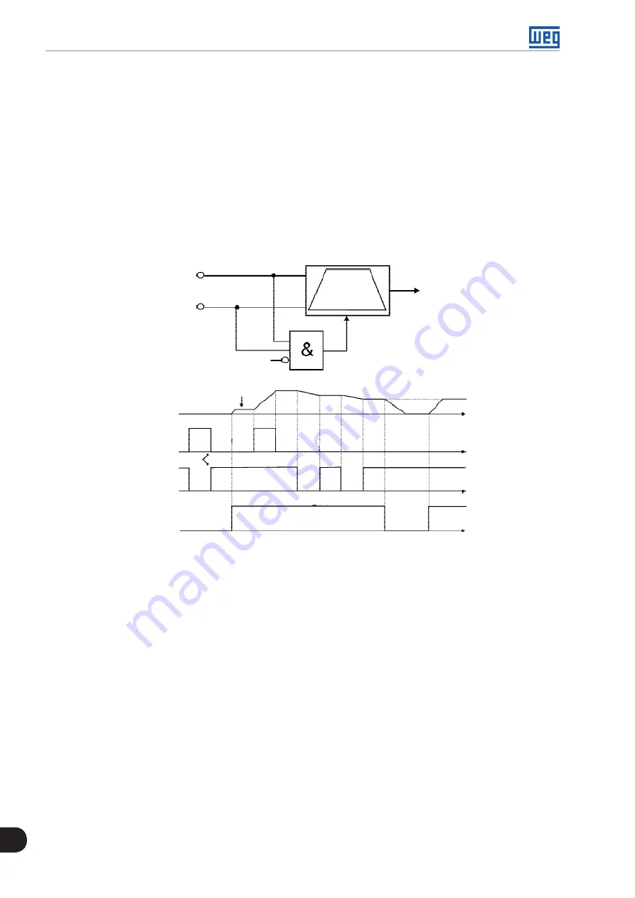
The CFW700 has the ELECTRONIC POTENTIOMETER (EP) function that allows the speed reference to be
adjusted via two digital inputs, one for accelerating and another for decelerating the motor.
With the inverter enabled and the DIx digital input set to “Function 1 of the Application (Accelerate)” activated,
the motor is accelerated according to the programmed acceleration ramp up to the maximum speed. If only
the DIx digital input set to “Function 2 of the Application (Decelerate)” is active and the inverter is enabled, the
motor speed is decreased according to the programmed deceleration ramp up to minimum speed. If both inputs
are active, the motor will decelerate for safety reasons. With the inverter disabled, DIx digital inputs are ignored
unless both are active, which the speed reference is set to 0 rpm. The following figure illustrates this condition.
Digital
Inputs
Minimum
Speed
Reset
Reset
Output
Speed
Increase
Decrease
Acceleration
Enabling
Time
Time
Time
Time
Open
24 V
24 V
DIx Increase
DIx Decrease
DIx Run/Stop
Deceleration
Open
24 V
Speed
Reference
Figure 19.5:
Operation of the Electronic Potentiometer Application (EP)
It is necessary to set P0221 or P0222 to 7 = SoftPLC for the operation of the electronic potentiometer application.
Definitions:
The Function 1 of the Application at P0263 to P0270 represents the Accelerate command.
The Function 2 of the Application at P0263 to P0270 represents the Decelerate command.
The accelerate command is done by one of the digital inputs (DI1 to DI8). It is necessary to set one of the
DI’s parameters (P0263 to P0270) to 20 = Function 1 of the Application. If more than one digital input is set
for this function, the logic operation will consider only the command of the high priority level digital input,
where: DI1>DI2>DI3>DI4>DI5>DI6>DI7>DI8. If any of the digital inputs is set, the following alarm message
will be displayed: “A750: Set a DI for Function 1 of the Application (Accelerate)” and the operation of the
application will not be enabled.
The decelerate command is also done by one of digital inputs (DI1 to DI8). However, it is necessary to set one
the DI’s parameters (P0263 to P0270) to 21 = Function 2 of the Application. If more than one digital input is
set for this function, the logic operation will consider only the command of the high priority level digital input,
where: DI1>DI2>DI3>DI4>DI5>DI6>DI7>DI8. If any of the digital inputs is set, the following alarm message will
be displayed: “A752: Set a DI for Function 2 of the Application (Decelerate)” and the operation of the application
will not be enabled.
Summary of Contents for CFW700
Page 2: ......
Page 4: ......
Page 8: ...Summary...
Page 34: ...2 General Information 2 4 CFW700...
Page 38: ...3 About the CFW700 3 4 CFW700...
Page 56: ...7 Starting up and Settings 7 4 CFW700...
Page 58: ...8 Available Control Types 8 2 CFW700...
Page 78: ...10 VVW Control 10 8 CFW700...
Page 158: ...13 Digital and Analog Inputs and Outputs 13 28 CFW700...


