


38 | CFW501
Technical Specifications
E
ng
lis
h
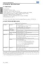
8 TECHNICAL SPECIFICATIONS
8.1 POWER DATA
Power Supply:
Tolerance: -15 % to +10 %.
Frequency: 50/60 Hz (48 Hz to 62 Hz).
Phase imbalance: ≤ 3 % of the rated phase-to-phase input voltage.
Overvoltage according to Category III (EN 61010/UL 508C).
Transient voltage according to Category III.
Maximum of 10 connections per hour (1 every 6 minutes).
Typical efficiency: ≥ 97 %.
For further information about the technical specifications, refer to
.
8.2 ELECTRONICS/GENERAL DATA
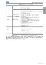
Table 8.1:
Electronics/general data
CONTROL
METHOD
Type of control:
- V/f (Scalar) with power saving function;
- V V W: Voltage vector control.
PWM SVM (Space Vector Modulation)
OUTPUT
FREQUENCY
0 to 500 Hz, resolution of 0.015 Hz.
PERFORMANCE V/f CONTROL
Speed regulation: 1 % of the rated speed (with slip compensation).
Speed variation range: 1:20.
VECTOR CONTROL
(V V W)
Speed regulation: 1 % of the rated speed.
Speed variation range: 1:30.
INPUTS
(*)
ANALOG
2 insulated inputs. Levels: (0 to 10) V or (0 a 20) mA or (4 to 20) mA.
Linearity error ≤ 0.25 %.
Impedance: 100 kΩ for voltage input, 500 Ω for current input.
Programmable functions.
Maximum voltage permitted in the input: 30 Vdc.
DIGITAL
4 insulated inputs.
Programmable functions:
- active high (PNP): maximum low level of 15 Vdc.
minimum high level of 20 Vdc.
- active low (NPN): maximum low level of 5 Vdc.
minimum high level of 9 Vdc.
Maximum input voltage of 30 Vdc.
Input current: 4.5 mA.
Maximum input current: 5.5 mA.
OUTPUTS
(*)
ANALOG
1 insulated output. Levels (0 to 10) V or (0 to 20) mA or (4 to 20) mA.
Linearity error ≤ 0.25 %.
Programmable functions.
RL ≥ 10 kΩ (0 to 10 V) or RL ≤ 500 Ω (0 to 20 mA / 4 to 20 mA).
(*)
The number and/or type of analog/digital inputs/outputs may vary. Depending on the Plug-in module (accessory) used. For
the table above, it was considered the CFW500-CRS485 plug-in module. For further information, refer to the programming
manual and the guide supplied with the optional item or in the CD-ROM.
(**)
The maximum capacity of 150 mA must be considered adding the load of the 24-V power supply and transistor output, that
is, the sum of the consumption of both must not exceed 150 mA.