


CFW501 | 21
Installation and Connection
E
ng
lis
h
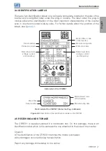
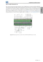
3.3 INSTALLATIONS ACCORDING TO EUROPEAN DIRECTIVE OF
ELECTROMAGNETIC COMPATIBILITY
Inverters with the option C2 or C3 (CFW501...C...) feature internal RFI filter to reduce
the electromagnetic interference. Those inverters, when properly installed, meet the
requirements of the directive of the electromagnetic compatibility.
The CFW501 inverter series was developed for professional applications only.
Therefore, the emission limits of harmonic currents by the standards EN 61000-3-2
and EN 61000-3-2/A 14 are not applicable.
3.3.1 Conformal Installation
1. Inverters with option internal RFI filter CFW501...C... (with grounding switch of the
capacitors of the internal RFI filter in the position
). Check the location of the
2. Shielded output cables (motor cables) with shield connected at both ends, motor
and inverter, by means of a low impedance to high frequency connection.
Maximum motor cable length and conduced and radiated emission levels according
. If a lower conducted emission level and/or longer motor cable is desired,
then an external RFI filter must be used at the inverter input. For more information
(RFI filter commercial reference, motor cable length and emission levels) refer to the
3. Shielded control cables, keeping the separation distance from other cables according
.
4. Grounding of the inverter according to instruction of the item
.
5. Grounded power supply.