


14 | CFW501
Installation and Connection
E
ng
lis
h
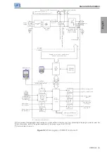
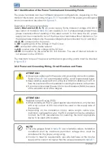
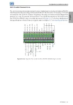
3.2.3.3 Dynamic Braking
NOTE!
The dynamic braking is available from frame B.
Refer to
for the following specifications of the dynamic braking: maximum
current, resistance, effective current
(*)
and cable gauge.
Input power
supply
Thermostat
Brake
resistor
Relay
Command
power supply
Contactor
BR
+Ud
R
S
T
Figure 3.2:
Installation of brake resistor
(*)
The effective braking current can be calculated as follows:
I
effective
= I
max
. t
br
(min)
√ 5
seeing that: t
br
corresponds to the sum of the braking actuation times during the most
severe cycle of five minutes.
The power of the brake resistor must be calculated considering the deceleration time,
the inertia of the load and of the resistive torque.