CFW501 | 129
Appendix A / Anexo A
A
pp
en
d
ix
A
A
ne
xo
A
APPENDIX A – FIGURES
ANEXO A – FIGURAS
ANEXO A – FIGURAS
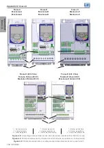
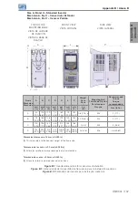
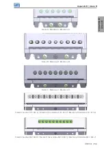
Frame A, B and C
Tamaño A, B y C
Mecânica A, B e C
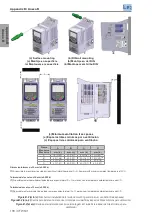
Frame D
Tamaño D
Mecânica D
3
4
2
6
1
5
2
3
4
5
1
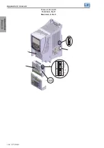
1 – Mounting supports (for through the
wall mounting)
2 – Mounting supports (for DIN rail
mounting)
3 – Fan with mounting support
4 – Plug-in module
5 – HMI
6 – Front Cover
1 – Soporte de fijación (para el montaje
en superficie)
2 – Soporte de fijación (para el montaje
en carril DIN)
3 – Ventilador con soporte de fijación
4 – Módulo plug-in
5 – HMI
6 – Tapa frontal
1 – Suporte de fixação (para montagem
em superfície)
2 – Suporte de fixação (para montagem
em trilho DIN)
3 – Ventilador com suporte de fixação
4 – Módulo plug-in
5 – HMI
6 – Tampa frontal
Figure A.1:
Main components of the CFW501
Figura A.1:
Principales componentes del CFW501
Figura A.1:
Componentes principais do CFW501


