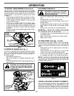
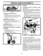
Weed Eater S165H42A Owner'S Manual Download Page 14

14

FIG. 9

MOWING TIPS

Mower should be properly leveled for best mowing
performance.  See “TO LEVEL MOWER HOUSING” in
the Service and Adjustments section of this manual.

The left hand side of mower should be used for trimming.

Drive so that clippings are discharged onto the area that
has been cut.  Have the cut area to the right of the
machine.  This will result in a more even distribution of
clippings and more uniform cutting.

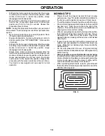
When mowing large areas, start by turning to the right so
that clippings will discharge away from shrubs, fences,
driveways, etc.  After one or two rounds, mow in the
opposite direction making left hand turns until finished
(See Fig. 9).

If grass is extremely tall, it should be mowed twice to
reduce load and possible fire hazard from dried clip-
pings.  Make first cut relatively high; the second to the
desired height.

Do not mow grass when it is wet.  Wet grass will plug
mower and leave undesirable clumps.  Allow grass to dry
before mowing.

Always operate engine at full throttle when mowing
to assure better mowing performance and proper dis-
charge of material.  Regulate ground speed by selecting
a low enough gear to give the mower cutting perfor-
mance as well as the quality of cut desired.

When operating attachments, select a ground speed
that will suit the terrain and give best performance of the
attachment being used.

OPERATION

Sitting in the tractor seat, start engine. After the engine
is running, move throttle control to slow position. With
motion control lever in neutral (N) position, slowly
disengage clutch/brake pedal.

Move motion control lever to full forward position and
hold for five (5) seconds. Move lever to full reverse
position and hold for five (5) seconds. Repeat this
procedure three (3) times.

NOTE:  During this procedure there will be no movement of
drive wheels. The air is being removed from hydraulic drive
system.

Move motion control lever to neutral (N) position. Shut-
off engine and set parking brake.

Engage transmission by placing freewheel control in
driving position (See “TO TRANSPORT” in this section
of manual).

Sitting in the tractor  seat, start engine. After the engine
is running, move throttle control to half (1/2) speed. With
motion control lever in neutral (N) position, slowly
disengage clutch/brake pedal.

Slowly move motion control lever forward, after the
tractor moves approximately five (5) feet, slowly move
motion control lever to reverse position. After the tractor
moves approximately five (5) feet return the motion
control lever to the neutral (N) position. Repeat this
procedure with the motion control lever three (3) times.

Your tractor is now purged and now ready for normal
operation.

Summary of Contents for S165H42A

Page 1: ...AL MODEL NO S165H42A 16 5 HP 42 Inch LawnTractor For Parts and Service contact our authorized distributor call 1 800 849 1297 For Technical Assistance call 1 800 829 5886 177019 Rev 1 01 30 01 RH PRIN...

Page 2: ...the slope Safe Operation Practices for Ride On Mowers IMPORTANT THIS CUTTING MACHINE IS CAPABLE OF AMPUTATING HANDS AND FEET AND THROWING OBJECTS FAILURE TO OBSERVE THE FOLLOWING SAFETY INSTRUCTIONS C...

Page 3: ...ctices for Ride On Mowers SAFETY RULES SAFETY RULES 2 3 PRODUCT SPECIFICATIONS 4 CUSTOMER RESPONSIBILITIES 4 15 18 ASSEMBLY 6 8 OPERATION 9 14 MAINTENANCE SCHEDULE 15 SERVICE AND ADJUSTMENTS 19 23 STO...

Page 4: ...s to service or repair this tractor Please read and retain this manual The instructions will enable you to assemble and maintain your tractor properly Always observe the SAFETY RULES CUSTOMER RESPONSI...

Page 5: ...sher 1 Locknut 5 16 18 1 Hex Bolt 5 16 18 x 1 1 4 1 Hex Bolt 3 8 16 x 1 1 Lockwasher 3 8 Steering Boot Steering Extension Shaft Steering Wheel Adapter 1 Bolt 1 Washer 17 32 x 1 3 16 x 12 Gauge Seat 2...

Page 6: ...hex bolt and locknut Tighten securely Place tabs of steering boot over tab slots in dash and push down to secure INSTALL STEERING WHEEL Position front wheels of the tractor so they are pointing straig...

Page 7: ...ine Afterenginehasstarted movethrottle control to idle position Releaseparkingbrake Slowlymovethemotioncontrolleverforwardandslowly drive tractor off skid Applybraketostoptractor setparkingbrakeandpla...

Page 8: ...clean regular unleaded gasoline Become familiar with all controls their location and function Operate them before you start the engine Be sure brake system is in safe operating condition Itisimportant...

Page 9: ...RD FAST SLOW ENGINE ON ENGINE OFF OIL PRESSURE LIGHTS ON FUEL CHOKE MOWER HEIGHT PARKING BRAKE LOCKED UNLOCKED REVERSE NEUTRAL HIGH LOW ATTACHMENT CLUTCH ENGAGED MOWER LIFT DANGER KEEP HANDS AND FEET...

Page 10: ...TCH BRAKE PEDAL Used for declutching and brak ing the tractor and starting the engine PARKINGBRAKE Locksclutch brakepedalintothebrake position FREEWHEEL CONTROL Disengages transmission for pushing or...

Page 11: ...hrottle control to slow position NOTE Failure to move throttle control to slow position and allowingenginetoidlebeforestoppingmaycauseengineto backfire Turn ignition key to OFF position and remove key...

Page 12: ...e slot and release so it is held in the disengaged position Do not push or tow tractor at more than two 2 MPH To reengage transmission reverse above procedure NOTE To protect hood from damage when tra...

Page 13: ...on dipstick is reached Do not overfill For cold weather operation you should change oil for easier starting See OIL VISCOSITY CHART in the Customer Responsibilities section of this manual To change e...

Page 14: ...ttachments select a ground speed thatwillsuittheterrainandgivebestperformanceofthe attachment being used OPERATION Sitting in the tractor seat start engine After the engine is running move throttle co...

Page 15: ...ery 7 Tighten front axle pivot bolt to 35 ft lbs maximum Do not overtighten 1 12 3 2 5 5 6 7 GENERAL RECOMMENDATIONS The warranty on this tractor does not cover items that have beensubjectedtooperator...

Page 16: ...nte nance BRAKE OPERATION If tractor requires more than six 6 feet stopping distance at high speed in highest gear then brake must be adjusted See TOADJUSTBRAKE intheServiceandAdjustments section of t...

Page 17: ...40 F C 32 10 10 60 5W 30 SAE 30 NOTE Although multi viscosity oils 5W30 10W30 etc improve starting in cold weather these multi viscosity oils will result in increased oil consumption when used above 3...

Page 18: ...romoverheating Hoodandengine blower housing must be removed to clean engine cooling fins Remove hood See TO REMOVE HOOD AND GRILL ASSEMBLY intheServiceandAdjustmentssectionof this manual Removescrewss...

Page 19: ...CTOR TO REMOVE MOWER See Fig 16 Mower will be easier to remove from the right side of tractor Place attachment clutch in DISENGAGED position Move attachment lift lever forward to lower mower to its lo...

Page 20: ...ne side of mower loosen lift link adjustment nut on that side NOTE Threefullturnsofadjustmentnutwillchangemower height about 1 8 Recheck measurements after adjusting FRONT TO BACK ADJUSTMENT See Figs...

Page 21: ...See PURGE TRANSMIS SION in the Operation section of this manual ADJUSTMENT BOLT FIG 24 NEUTRAL LOCK GATE MOTION CONTROL LEVER TO ADJUST STEERING WHEEL ALIGNMENT If steering wheel crossbars are not hor...

Page 22: ...t square key Replace washers and snap retaining ring securely in axle groove Replace axle cover NOTE To seal tire punctures and prevent flat tires due to slow leaks tire sealant may be purchased from...

Page 23: ...eck adjustment as described below before loosening cable If adjustment is necessary proceed as follows Withenginenotrunning movethrottlecontrolleverfrom slowtochokeposition Slowlymoveleverfromchoketo...

Page 24: ...G IN ESSENTIAL FUEL SYSTEM PARTS SUCH AS CARBURETOR FUEL FILTER FUEL HOSE OR TANK DURING STORAGE ALSO EXPERIENCE INDICATES THAT ALCOHOL BLENDED FUELS CALLED GASOHOL OR USING ETHANOL OR METHANOL CAN AT...

Page 25: ...eck replace ignition switch 8 Faulty solenoid or starter 8 Check replace solenoid or starter 9 Faulty operator presence switch es 9 Contact an authorized service center department Engine clicks but wi...

Page 26: ...place sharpen blade Tighten blade bolt 7 Buildup of grass leaves and trash under mower 7 Clean underside of mower housing 8 Mower drive belt worn 8 Replace mower drive belt 9 Blades improperly install...

Page 27: ...R TRACTOR IS EQUIPPED WITH A SPECIAL ALTERNATOR SYSTEM THE LIGHTS ARE NOT CONNECTED TO THE BATTERY BUT HAVE THEIR OWN ELECTRICAL SOURCE BECAUSE OF THIS THE BRIGHTNESS OF THE LIGHTS WILL CHANGE WITH EN...

Page 28: ...28 28 29 26 24 42 43 27 27 25 41 27 27 40 33 30 8 2 1 27 16 16 52 D C AM PE RE S 45 22 21 REPAIR PARTS TRACTOR MODEL NUMBER S165H42A ELECTRICAL...

Page 29: ...Ga 16 red 25 146147 Cable Battery 6 Ga w 16 wire red 26 175158 Fuse 27 73510400 Nut Keps Hex 1 4 20 unc 28 4207J Cable Ground 6 Ga 12 black 29 121305X Switch Plunger Nc Gray 30 175566 Switch Ign 33 1...

Page 30: ...MODEL NUMBER S165H42A CHASSIS AND ENCLOSURES 37 37 3 2 35 3 26 3 35 26 33 10 34 1 208 11 17 29 28 208 13 207 20 207 23 12 51 57 53 52 54 55 24 26 25 26 25 3 31 24 30 209 8 209 6 16 9 15 209 209 5 5 1...

Page 31: ...Ga 26 73800600 Nut Lock Hex w Insert 3 8 16 UNC 28 150407 Grill Lens Asm 29 150209X599 LensQuadra 30 169467X550 Fender Asm 31 136619 BracketFender 33 105476X550 Footrest Lh 34 105475X550 Footrest Rh...

Page 32: ...56 64 65 212 63 116 70 57 66 27 51 48 151 202 49 47 50 120 150 156 166 165 82 168 163 14 164 21 8 10 83 159 161 198 158 162 171 169 29 28 32 30 52 32 53 35 55 36 62 35 36 22 34 61 16 1 77 77 30 61 52...

Page 33: ...4 Bolt Hex 65 10040700 Washer 66 154778 Keeper Belt Engine Hydro 69 142432 Screw 70 134683 Keeper Belt Engine 71 169183 Strap Torque Lh Hydro 72 19132012 Washer 13 32 x 1 1 4 x 12 Gauge 73 169182 Stra...

Page 34: ...MBER S165H42A STEERING ASSEMBLY 62 44 51 54 5 9 5 7 7 9 4 3 32 43 6 43 8 18 19 22 27 23 40 66 29 25 79 8 10 40 11 8 6 9 46 46 8 6 9 2 47 47 17 26 30 28 1 41 42 37 36 37 38 63 11 39 11 80 68 67 67 67 1...

Page 35: ...4 30 76020412 Pin 32 130465 Rod Tie Wire Form 19 75 Mech 36 155099 Bushing Strg 5 8 Id Dash 37 152927 Screw TT 10 32 x 5 x 3 8 Flange 38 133742X428 Insert Cap Strg 39 19133812 Washer 13 32 x 2 3 8 x 1...

Page 36: ...36 REPAIR PARTS TRACTOR MODEL NUMBER S165H42A ENGINE 2 1 OPTIONAL EQUIPMENT Spark Arrester 29 33 37 33 40 62 13 4 85 78 78 81 3 16 23 45 14 38 44 46 32 31...

Page 37: ...be Drain Oil Easy 16 11050600 Washer Lock Ext Tooth 3 8 23 169837 ShieldBrowning 29 137180 ArrestorSpark 31 174642 Tank Fuel 2 00 Fr 32 140527 Cap Asm Fuel 33 123487X Clamp Hose Blk 37 137040 Line Fue...

Page 38: ...Washer 17 32 x 1 3 16 x 12 Ga 25 127018X Bolt Shoulder 5 16 18 x 62 26 10040800 Lockwasher 26 23 1 24 16 15 12 13 17 25 4 3 8 9 7 8 9 7 2 6 22 21 5 10 5 14 1 140116 Seat 2 140551 Bracket Pnt Pivot Sea...

Page 39: ...34 Sealant Tire 10 oz Tube NOTE All component dimensions given in U S inches 1 inch 25 4 mm KEY PART NO NO DESCRIPTION KEY PART NO NO DESCRIPTION 12 177430 DecalFender 14 160396 Decal V belt Schematic...

Page 40: ...40 REPAIR PARTS TRACTOR MODEL NUMBER S165H42A MOWER LIFT 15 20 16 1718 20 20 15 20 4 5 6 2 3 1 6 5 4 7 8 12 11 31 32 31 32 19 19 13 13 13 13...

Page 41: ...GripHandle 8 124526X ButtonPlunger 11 139865 Link Lift Lh 12 139866 Link Lift Rh 13 4939M RetainerSpring 15 173288 Link Front 16 73350800 Nut Jam Hex 1 2 13 Unc 17 130171 Trunnion Blk Zinc 18 7380080...

Page 42: ...48 145 150 45 144 147 147 142 149 142 49 50 51 54 52 53 55 56 34 1 46 44 21 22 24 25 26 27 2 28 29 23 21 21 21 18 18 20 2 48 59 19 4 3 5 6 21 40 143 36 40 37 40 159 152 151 153 154 157 158 67 153 156...

Page 43: ...18 UNC 53 131845 Arm Assembly Pad Brake 54 133943 Washer Hardened 55 155046 Arm Idler 56 165723 Spacer Retainer 59 141043 Guard TUV Idler 67 106932X Knob 68 144959 V Belt 42 Mower 90 74760616 Bolt Fin...

Page 44: ...44 SERVICE NOTES...

Page 45: ...limited to 90 days from the date of original purchase 5 This Warranty applies only to products which have been properly assembled adjusted operated and main tained in accordance with the instructions...

Page 46: ...the Power Train Component and parts The cost of normal maintenance and replacement of service items which are not defective shall be paid for by the original purchaser C Securing Warranty Service War...

Page 47: ...IGHTING GUIDE ONLY RIDE UP AND DOWN HILL NOT ACROSS HILL SUGGESTED GUIDE FOR SIGHTING SLOPES FOR SAFE OPERATION Operate your Tractor up and down the face of slopes not greater than 15 never across the...

Page 48: ......

Reviews: