background image

CPR Touch XL, Control Unit


Index: 03  Date modified: 22/06/2022 

OI No.: BA MR 001-03 Steuereinheit CPR Touch XL EN.docx 

Page 6 of 70 

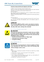
CORROSIVE!  

“Corrosive”  denotes  a  safety  notice  which,  if  disregarded  when 
handling chemicals, may lead to 

injuries

 or 

material damage


ESD SENSITIVE!  

“ESD  SENSITIVE”  denotes  electronic  components  that  may  be 
damaged  by  electrostatic  discharges.  The  generally  accepted  safety 
precautions for ESD-sensitive devices must be observed when handling 
the devices! 
 

NOTICE!  

A  notice  denotes  information  which,  if  disregarded,  may  lead  to 

malfunctions.


Tip! 

A “Tip” denotes information that may result in

 improvements in the 

operating process


Mandatory sign 

Use face protection! 


Mandatory sign  

Use protective gloves!


In accordance with DIN EN 374, protective 

gloves against chemicals and microorganisms


Mandatory sign 

Use protective apron!


Mandatory sign 

Use protective boots!


Summary of Contents for CPR Touch XL

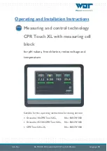
Page 1: ...ions Measuring and control technology CPR Touch XL with measuring cell block for pH values free chlorine redox voltage and temperature Suitable for the operating instructions for dosing devices Granud...

Page 2: ...4 Installation 17 4 1 Select the installation site 17 4 2 Installation instructions installation suggestion 17 4 3 Mechanical installation 17 4 4 Hydraulic installation 17 4 5 Electrical installation...

Page 3: ...ation 48 7 1 3 pH measurement calibrate pH electrode 48 7 1 4 Combination reference return electrode 49 7 1 5 Chlorine electrode exchange the gasket set 49 7 1 6 Redox electrode exchange the gasket se...

Page 4: ...er languages even in excerpts is only permitted with the express authorisation of the company WDT Werner Dosiertechnik GmbH Co KG These operating instructions are an English translation of the origina...

Page 5: ...CPR Touch XL 2S No OI SW 004 1 2 Target group Only our authorised partners and people who have been trained in the device functions are permitted to work on the system provided that they have read and...

Page 6: ...y electrostatic discharges The generally accepted safety precautions for ESD sensitive devices must be observed when handling the devices NOTICE A notice denotes information which if disregarded may l...

Page 7: ...tear For these we assume a warranty of 1 2 year Our merchandise management programme requires an invoice for each delivery including warranty services When returning a defective component upon review...

Page 8: ...of the components used but we are unable to guarantee this over a period of several years For spare part orders we therefore always require the following data You can find these on the identification...

Page 9: ...IT safety The CPR Touch XL controller series allows remote access to data and control parameters by means of network compatible devices The operator is responsible for ensuring that only authorised pe...

Page 10: ...ntrol devices that dose caustic chemicals For this reason it is essential that you observe the safety information relating to the chemicals 2 2 2 Protective measures and rules of conduct ESD SENSITIVE...

Page 11: ...stem owner oblige every user to inform you immediately if they discover facts or irregularities that can be traced back to unlawful remote access 4 Technical measures to protect against access You as...

Page 12: ...he water treatment in swimming pools It is used for the following 3 dosing devices GRANUDOS 10 CPR Touch XL GRANUDOS 45 100 CPR Touch XL CPR Touch XL 2S The control unit has the following main functio...

Page 13: ...ution errors by the assembling personnel are thereby avoided as far as possible For transportation purposes both electrodes along with the glass shaft have been removed from the measuring cell and del...

Page 14: ...control valve 7 PMMA measuring cell block 8 Sampling tap 9 Prefilter for Type 2S optional for wall mounting 10 Redox electrode 11 Chlorine electrode 12 Measuring water inlet 13 Measuring water return...

Page 15: ...messages or fault indications 3 2 3 The measuring cell block The compact acrylic glass measuring cell block 7 is used to hold the electrodes dosing valves cleaning beads and the sampling tap The flow...

Page 16: ...x 80 non condensing Concentration hypochlorous acid max 0 1 12 rpm Granudos 45 max 0 2 Granudos 100 max 0 35 Room ventilation in and out According to DIN 19643 Material Housing PS Measuring water line...

Page 17: ...instructions installation suggestion See Operating Instructions Part 1 Dosing technology regarding the respective dosing device 4 3 Mechanical installation See Operating Instructions Part 1 Dosing tec...

Page 18: ...e device and at the two measuring water ball valves 6 x 1 Plastic pipe unions may only be fastened hand tight 5 2 Commissioning works Carry out the commissioning works in the sequence indicated 5 2 1...

Page 19: ...n connected the measuring water intake can be opened The flow volume can be adjusted at the flow control valve pos 6 The flow meter float pos 2 must be pushed toward the top in order to release the do...

Page 20: ...me with additional text based instructions A 7 touch screen allows the clear and easy operation of the microprocessor supported control of the CPR Touch XL 6 1 1 Operation display Display auto mode Th...

Page 21: ...e symbols depend on the firmware used i e the device type IN list general Red pH level container for pH control empty Yellow disinfection level container for disinfectant empty Blue flocculation level...

Page 22: ...he scope of functions a larger or smaller number of icons is displayed in the individual menu items The following symbols are only active in the GRANUDOS device variant IN list only for Granudos The p...

Page 23: ...e during the buffer filling Filling has been deactivated The buffer filling was cancelled by the CPR controller Filling occurred too slowly OUT list optional design with buffer tank Buffer tank fillin...

Page 24: ...he device is restarted the dosing delay is running during this time no dosing output is activated Software alarms are suppressed during this time The dosing delay must be set high enough to ensure tha...

Page 25: ...is additionally illustrated in red In the event of faults the corresponding symbol appears in the In list Alarms or faults must be pending for approx 5 seconds before an alarm is triggered With the b...

Page 26: ...done via the redox control function If this operation mode is selected the display in the start screen changes The measuring value for free chlorine is faded out When switching to redox control the do...

Page 27: ...hanges can only be made after the password has been entered After a password has been assigned please enter it in the operation data sheet Automatic Navigates to the start screen and automatic operati...

Page 28: ...isinfection Set disinfection control parameter Dosing performance Adjust the dosing performance to the basin size mV Redox alarm control Set redox voltage control parameter Temperature Set basin tempe...

Page 29: ...the dosing is blocked Important This fault must be acknowledged manually Control direction pH reduce or pH increase Cycle setting cycle time in seconds Main menu Settings pH Control type Proportional...

Page 30: ...GRANUDOS Control type top left Proportional e g peristaltic pumps 2 point on off e g solenoid valves electrolysis longer control times Alarm low lower alarm value P range The dosing works proportional...

Page 31: ...in seconds Manual dosing Switch between automatic and manual dosing The table shows the possible combinations of dosing motor with dosing screw and the resulting dosing performances of chlorine granu...

Page 32: ...ection Select the settings of the dosing performance in such a way that the chlorine dosing performance e g DIN indoor swimming pool 2 g m or outdoor swimming pool 10 g m pure chlorine to be provided...

Page 33: ...4 15 3 60 0 sec 30 sec 0 sec 90 sec Manual dosing Off On It is possible to change over to continuous manual dosing This may be required in the event of a fault with the measurement technology e g ele...

Page 34: ...automatic operation changes The measuring value for free chlorine is faded out Alarm low Lower alarm value P range The dosing works proportionally i e the higher the difference between setpoint and ac...

Page 35: ...Upper alarm value Offset for calibration of the temperature measurement Control Off On Operation mode Temperature display or Control Main menu Settings Dosing delay If the device is restarted the dos...

Page 36: ...In the Slave operation mode a signal from the central swimming pool control initiates the ECO operation The ECO output DIN contact is used for feedback to the central swimming pool control It may be...

Page 37: ...each day Times can be selected between 00 00 and 24 00 The colon must be entered as well Times that cover more than one day must be entered as two blocks for both days Example A desired night time op...

Page 38: ...and 9999 In the second line the password must be re entered If you place a green check mark next to Clear text the entered numbers are shown instead of white dots To change an active end user passwor...

Page 39: ...ings System Language Select your desired operator language Main menu Settings Shock chlorination With this menu you can adjust the dosing performance during a shock chlorination Please select a dosing...

Page 40: ...switches The changing activation of the switches is indicated by 0 open or 1 closed The fourth column displays the pin header SLx and the connectors Pinx x to which the switch is connected The fifth c...

Page 41: ...troller against unauthorised access Without password no further settings calibrations output tests etc are possible You can still browse the menu and view the data logging For future changes and adjus...

Page 42: ...by lightly touching it that day will be shown on a white background You can use the Event Log ICON to view the events of the selected day Main menu Log Data Log If Data Log is activated the measuring...

Page 43: ...an use the selected ICON to delete the Event Log and Data Log events for the selected day You can use the all ICON to delete all Event Log and Data Log events at once 6 2 5 Main menu Calibration pH Tw...

Page 44: ...optimal conductance voltage at 25 C is approx 59 mV pH Example pH7 pH4 3pH x 59 mV 177 mV NOTICE Notice regarding evaluation of the electrodes Cleaning notice At an offset voltage 41 mV the voltage va...

Page 45: ...t at the end of the menu In case of minor deviations the calibration is adopted immediately In case of deviations larger than 41 mV a cleaning notice is displayed In case of deviations larger than 61...

Page 46: ...device Since the measurement of free chlorine is subject to a certain inaccuracy approx 0 05 to 0 1 mg l calibration at low chlorine concentrations 0 2 is very unreliable Thus if the free chlorine sh...

Page 47: ...e can be chosen freely the fine tuning may also be done with other redox test solutions e g 220 mV or 640 mV When making a comparison please note the temperature dependence of the test solution See la...

Page 48: ...t Unscrew the filter hood from the bracket Remove the filter insert from the filter hood and wash the filter insert under running water Reinstall in the reverse order NOTICE A contaminated prefilter m...

Page 49: ...h your fingers 7 1 4 Combination reference return electrode For the combination reference return electrode PG13 5 blue a service life of one to two years may be expected as well The same safety measur...

Page 50: ...ng axle is identified by the plastic slotted screws on both sides The other side is equipped with two expanding rivets as pivot bearings Tip It is not necessary to completely remove the display lid fo...

Page 51: ...closed by moving it downward The upper lid lugs must now be unlocked and the lid pushed backward onto the main housing In order to ensure that it has been completely resealed press gently on the four...

Page 52: ...ne 2 If the flocculant container is not empty the empty switch is defective 3 If the suction lance is new check the float s functional direction 4 Flow measuring cell ALARM The flow through the measur...

Page 53: ...too high less water is siphoned off than is flowing into the flushing tub through the floating valve Dosing is stopped The booster pump keeps running 1 If the injector s suction capacity is OK a Floa...

Page 54: ...2 Stop buffer tank filling level switch working Check switchover valves for functioning 1 Buffer tank is overflowing or leaking a Stop buffer tank filling level and Level maximum alarm level switches...

Page 55: ...y with electrolyte and push it on the glass shaft of the pH electrode or the combination reference return electrode respectively The combination electrodes are frost resistant to approx 15 C if the te...

Page 56: ...perating instructions Part 1 regarding the respective dosing device 9 2 Wiring diagrams DANGER Risk of death due to high voltage All electrical work on the device must only be carried out by trained s...

Page 57: ...s Internal fuses may only be renewed once the voltage has been disconnected and secured against being reactivated Fuse in the control housing accessible from the outside Fuses Current Fuse type Functi...

Page 58: ...e 58 of 70 9 2 2 Wiring diagram I O Board for device 2S The figure shows the connected sensors or consumers respectively of the device version 2S with two peristaltic pumps Fuses Current Fuse type Fun...

Page 59: ...ontains the measurement converter for pH and redox measurements 1 Redox electrode black cable to redox electrode Platinum round blank 2 Mass shielding of the coaxial cable mV OPTIONAL 3 Mass shielding...

Page 60: ...001 03 Steuereinheit CPR Touch XL EN docx Page 60 of 70 9 2 4 Wiring diagram power pack with connection to the IO circuit board for device GR 10 CPR Fuses Current Fuse type Function F0 3 15 A slow 5...

Page 61: ...CPR Touch XL Control Unit Index 03 Date modified 22 06 2022 OI No BA MR 001 03 Steuereinheit CPR Touch XL EN docx Page 61 of 70 9 2 5 Wiring diagram I O circuit board FLOAT 8 for device GR 10 CPR...

Page 62: ...rd for device GR 45 100 CPR Fuse in the control housing accessible from the outside Fuses Current Fuse type Function 6 3 A 5 x 20 mm Primary fuse mains lead Fuses on the power pack Fuses Current Fuse...

Page 63: ...CPR Touch XL Control Unit Index 03 Date modified 22 06 2022 OI No BA MR 001 03 Steuereinheit CPR Touch XL EN docx Page 63 of 70 9 2 7 Wiring diagram I O circuit board FLOAT 8 for device GR 45 100 CPR...

Page 64: ...uch XL Control Unit Index 03 Date modified 22 06 2022 OI No BA MR 001 03 Steuereinheit CPR Touch XL EN docx Page 64 of 70 9 2 8 Wiring diagram buffer tank FLOAT 8 for the devices GR 10 CPR and GR 45 1...

Page 65: ...low 0 2 off 2 00 0 05 P range 0 3 0 05 2 00 0 05 Setpoint 0 6 mg l 0 1 2 0 8 0 0 05 Alarm high 0 8 0 1 2 0 8 0 off 0 05 Dosing time limit 30 minutes off 60 min 2 Range 0 2 0 2 or 0 8 3 Dosing perform...

Page 66: ...Saturday 00 00 24 00 Saturday 00 00 24 00 Saturday 00 00 24 00 Saturday 00 00 24 00 Sunday 00 00 24 00 Sunday 00 00 24 00 Sunday 00 00 24 00 Sunday 00 00 24 00 12 System Password End user 0000 9999 1...

Page 67: ...performance pH 100 8 sec 1 04 100 Disinfection 100 15 sec 0 55 100 Cycle time 30 Sec 30 360 sec 30 Manual dosing Off Off On 4 Parameter mV Redox Alarm low 600 mV 400 900 mV 10 Alarm high 800 mV 500 99...

Page 68: ...Saturday 00 00 24 00 Saturday 00 00 24 00 Saturday 00 00 24 00 Saturday 00 00 24 00 Sunday 00 00 24 00 Sunday 00 00 24 00 Sunday 00 00 24 00 Sunday 00 00 24 00 12 System Password End user 0000 9999 1...

Page 69: ...e complete 11980 Chlorine electrode insert gold 19 mm 17957 Redox electrode complete 11984 Redox electrode insert platinum 14 mm 11986 Flow through fitting Measuring cell CPR Touch 24271 1 Maintenance...

Page 70: ...2 06 2022 OI No BA MR 001 03 Steuereinheit CPR Touch XL EN docx Page 70 of 70 10 Appendices Personal notes You can use the following lines for personal notes e g regarding conducted service tasks or s...

Reviews: