


18
Part No. 917543 Rev. A
November 1992
3.6.1.
Photocoupler, continued
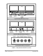
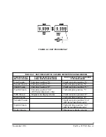
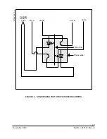
In blending dispensers the LED’s in each photocoupler are wired in series, as
shown in Figure 3-4. Because of this a problem in one of the photocouplers
can cause symptoms to be shown on the other end grade. For instance if one
of the LED’s in the Lo product photocoupler was to become an open circuit
the five volts would not be supplied to that LED in the Hi product
photocoupler. This would cause symptoms to appear on any Hi product sales.
3.6.2.
Pulser Disc
The pulser disc is a plastic disc with square holes cut around its outer edge. It
is connected to a shaft which is turned by the meter. The holes in the edge of
the disc pass between the LED’s and the phototransistors. This alternately
blocks and reveals the infrared beam to the phototransistors creating the
pulses.
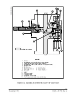
3.7.
SUCTION PUMP MOTOR
The pump motor used in Wayne suction pumps can be either a 1/3 or 3/4 horsepower
motor. Either of these two motors can be operated on either 110 VAC or 220 VAC,
depending on a switch setting. The voltage selection switch is located on the side of the
motor, and is secured by a sheet metal screw. To change the operation of the motor:
•
Remove the sheet metal screw which holds the switch in position.
•
Move the selector switch to the desired location.
•
Replace the screw to lock the switch in its new setting.
The pump motors are switched on by a relay located in the dispenser junction box. This
relay is pre-wired to the relay select line from the solenoid drive board. The load side of
the relay contacts are factory wired, therefore, the only on-site connections which need be
made are the two input wires to the relay contactors.
3.8.
BLEND MOTOR
(Blenders only) The blend motor is an electrical stepper motor which is used to adjust
the blend valve as product is being dispensed. The stepper motor receives voltage pulses
from the solenoid drive board; each of these pulses causes the motor to move a known
amount. A linkage interconnects the motor and the blend valve; therefore as the motor
moves the blend valve moves with it. The blend motor, one for each side of the dis-
penser, is located in the dispenser junction box.
Summary of Contents for Vista Series
Page 1: ...SERVICE Vista Blending and Non blending Suction Pumps and Remote Dispensers...
Page 4: ...Part No 917543 Rev A November 1992...
Page 12: ...x Part No 917543 Rev A November 1992...
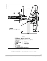
Page 34: ...22 Part No 917543 Rev A November 1992 FIGURE 4 1 NOZZLE BOOT ASSEMBLY WITH MICRO SWITCH...
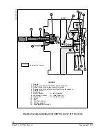
Page 35: ...23 November 1992 Part No 917543 Rev A FIGURE 4 2 NOZZLE BOOT ASSEMBLY WITH TILT SWITCH...
Page 36: ...24 Part No 917543 Rev A November 1992...
Page 53: ...41 November 1992 Part No 917543 Rev A FIGURE 5 7 METER CUTAWAY...
Page 54: ...42 Part No 917543 Rev A November 1992 FIGURE 5 8 METER ADJUSTMENT...
Page 58: ...46 Part No 917543 Rev A November 1992...
Page 69: ...57 November 1992 Part No 917543 Rev A FIGURE 7 1 REPLACING THE DUPLEX II COMPUTER...
Page 71: ...59 November 1992 Part No 917543 Rev A FIGURE 7 2 REPLACING THE INTRINSIC SAFE BARRIER BOARD...
Page 72: ...60 Part No 917543 Rev A November 1992 FIGURE 7 3 REPLACING THE INTEGRATED DISPLAY BOARD...
Page 75: ...63 November 1992 Part No 917543 Rev A FIGURE 7 5 REPLACING THE SOLENOID DRIVE BOARD...
Page 82: ...70 Part No 917543 Rev A November 1992...
Page 84: ...72 Part No 917543 Rev A November 1992...
Page 106: ...94 Part No 917543 Rev A November 1992...
Page 110: ...98 Part No 917543 Rev A November 1992 FIGURE B 4 THE DEM IN THE SERVICE POSITION...
Page 112: ...100 Part No 917543 Rev A November 1992 FIGURE B 6 DUPLEX II COMPUTERS J3 CONNECTOR PINOUT...
Page 114: ...102 Part No 917543 Rev A November 1992 FIGURE B 8 DUPLEX II COMPUTERS J11 CONNECTOR PINOUT...
Page 115: ...103 November 1992 Part No 917543 Rev A FIGURE B 9 DUPLEX II COMPUTERS J6 CONNECTOR PINOUT...
Page 116: ...104 Part No 917543 Rev A November 1992 FIGURE B 10 DUPLEX II COMUTERS J1 CONNECTOR PINOUT...
Page 125: ...113 November 1992 Part No 917543 Rev A FIGURE B 18B 4 PRODUCT SOLENOID DRIVE BOARD...
Page 126: ...114 Part No 917543 Rev A November 1992 FIGURE B 18C BLENDER SOLENOID DRIVE BOARD...
Page 133: ...121 November 1992 Part No 917543 Rev A FIGURE B 24 MANUALLY TURNING THE PHOTOCOUPLER...
Page 139: ...127 November 1992 Part No 917543 Rev A FIGURE B 29 LIGHTED CASH CREDIT INTERFACE BOARD...
Page 144: ...132 Part No 917543 Rev A November 1992...
Page 145: ...133 November 1992 Part No 917543 Rev A APPENDIX C DISPENSER INTERNAL WIRING DIAGRAMS...
Page 146: ...134 Part No 917543 Rev A November 1992...
Page 150: ...138 Part No 917543 Rev A November 1992 1 6560 D INTERNAL WIRING DIAGRAM V390D...
Page 151: ...139 November 1992 Part No 917543 Rev A 3 6560 D INTERNAL WIRING DIAGRAM V399D...
Page 152: ...140 Part No 917543 Rev A November 1992 5 6560 D INTERNAL WIRING DIAGRAM V490D...
Page 153: ...141 November 1992 Part No 917543 Rev A 7 6560 D INTERNAL WIRING DIAGRAM V590D...
Page 154: ...142 Part No 917543 Rev A November 1992 9 6560 D INTERNAL WIRING DIAGRAM V387D...
Page 155: ...143 November 1992 Part No 917543 Rev A 11 6560 D INTERNAL WIRING DIAGRAM V390P...
Page 156: ...144 Part No 917543 Rev A November 1992 12 6560 D INTERNAL WIRING DIAGRAM V585D...
Page 157: ...145 November 1992 Part No 917543 Rev A 13 6560 D INTERNAL WIRING DIAGRAM V395D...
Page 160: ...148 Part No 917543 Rev A November 1992...
Page 162: ...150 Part No 917543 Rev A November 1992 FLOWCHART D1 PULSER FAILURE ERROR CODE XX 05 2...