


3
November 1992
Part No. 917543 Rev. A
1.1.
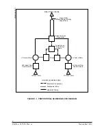
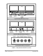
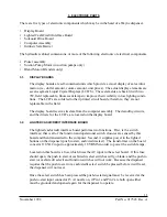
THE BLENDING PROCESS PROPORTIONAL BLENDERS (see Figure 1-1)
Proportional blenders have two grades of fuel input to the dispenser. The dispenser can
then use these grades to “produce” as many as five different grades output to the nozzle.
Two of these are the input grades, the other three are a mix of the two input grades.
These intermediate grades are produced by mixing the two input grades at some propor-
tion. The proportion which is used will determine the octane rating of the intermediate
grade.
There are two separate sets of hydraulics inside the proportional blender. One of these
sets is used to control flow of the low octane input (also called the LO feedstock), and the
other is used to control the high octane input (also called the HI feedstock). The heart of
the hydraulics in proportional blending dispensers is the blend valve. The HI and LO
feedstocks are each input to separate chambers in the blend valve; the blend valve is
designed in such a way that the outputs from these chambers can be controlled. By
manipulating the valve the flow from one chamber can be restricted while the flow from
the other is increased, changing the ratio of one product to the other. The hydraulics
continue to be separate until the two products are mixed at the hose outlet.
The computer continually senses the flow rate of each end grade and adjusts the blend
valve in order to maintain the correct blend ratio. If for some reason the correct blend
ratio cannot be obtained the computer will shut the sale down and generate an fault code.
1.2.
THE BLENDING PROCESS FIXED RATIO BLENDERS
Fixed ratio blenders differ from proportional blenders in that only one blended product is
available. This blended product is dispensed from the blended product hose (see Figure
1-2). The feedstocks are dispensed from separate hoses.
Because the blend ratio output from the blend hose cannot be changed from one sale to
the next, the mixing of the end grades can take place immediately after the blend valve.
Summary of Contents for Vista Series
Page 1: ...SERVICE Vista Blending and Non blending Suction Pumps and Remote Dispensers...
Page 4: ...Part No 917543 Rev A November 1992...
Page 12: ...x Part No 917543 Rev A November 1992...
Page 34: ...22 Part No 917543 Rev A November 1992 FIGURE 4 1 NOZZLE BOOT ASSEMBLY WITH MICRO SWITCH...
Page 35: ...23 November 1992 Part No 917543 Rev A FIGURE 4 2 NOZZLE BOOT ASSEMBLY WITH TILT SWITCH...
Page 36: ...24 Part No 917543 Rev A November 1992...
Page 53: ...41 November 1992 Part No 917543 Rev A FIGURE 5 7 METER CUTAWAY...
Page 54: ...42 Part No 917543 Rev A November 1992 FIGURE 5 8 METER ADJUSTMENT...
Page 58: ...46 Part No 917543 Rev A November 1992...
Page 69: ...57 November 1992 Part No 917543 Rev A FIGURE 7 1 REPLACING THE DUPLEX II COMPUTER...
Page 71: ...59 November 1992 Part No 917543 Rev A FIGURE 7 2 REPLACING THE INTRINSIC SAFE BARRIER BOARD...
Page 72: ...60 Part No 917543 Rev A November 1992 FIGURE 7 3 REPLACING THE INTEGRATED DISPLAY BOARD...
Page 75: ...63 November 1992 Part No 917543 Rev A FIGURE 7 5 REPLACING THE SOLENOID DRIVE BOARD...
Page 82: ...70 Part No 917543 Rev A November 1992...
Page 84: ...72 Part No 917543 Rev A November 1992...
Page 106: ...94 Part No 917543 Rev A November 1992...
Page 110: ...98 Part No 917543 Rev A November 1992 FIGURE B 4 THE DEM IN THE SERVICE POSITION...
Page 112: ...100 Part No 917543 Rev A November 1992 FIGURE B 6 DUPLEX II COMPUTERS J3 CONNECTOR PINOUT...
Page 114: ...102 Part No 917543 Rev A November 1992 FIGURE B 8 DUPLEX II COMPUTERS J11 CONNECTOR PINOUT...
Page 115: ...103 November 1992 Part No 917543 Rev A FIGURE B 9 DUPLEX II COMPUTERS J6 CONNECTOR PINOUT...
Page 116: ...104 Part No 917543 Rev A November 1992 FIGURE B 10 DUPLEX II COMUTERS J1 CONNECTOR PINOUT...
Page 125: ...113 November 1992 Part No 917543 Rev A FIGURE B 18B 4 PRODUCT SOLENOID DRIVE BOARD...
Page 126: ...114 Part No 917543 Rev A November 1992 FIGURE B 18C BLENDER SOLENOID DRIVE BOARD...
Page 133: ...121 November 1992 Part No 917543 Rev A FIGURE B 24 MANUALLY TURNING THE PHOTOCOUPLER...
Page 139: ...127 November 1992 Part No 917543 Rev A FIGURE B 29 LIGHTED CASH CREDIT INTERFACE BOARD...
Page 144: ...132 Part No 917543 Rev A November 1992...
Page 145: ...133 November 1992 Part No 917543 Rev A APPENDIX C DISPENSER INTERNAL WIRING DIAGRAMS...
Page 146: ...134 Part No 917543 Rev A November 1992...
Page 150: ...138 Part No 917543 Rev A November 1992 1 6560 D INTERNAL WIRING DIAGRAM V390D...
Page 151: ...139 November 1992 Part No 917543 Rev A 3 6560 D INTERNAL WIRING DIAGRAM V399D...
Page 152: ...140 Part No 917543 Rev A November 1992 5 6560 D INTERNAL WIRING DIAGRAM V490D...
Page 153: ...141 November 1992 Part No 917543 Rev A 7 6560 D INTERNAL WIRING DIAGRAM V590D...
Page 154: ...142 Part No 917543 Rev A November 1992 9 6560 D INTERNAL WIRING DIAGRAM V387D...
Page 155: ...143 November 1992 Part No 917543 Rev A 11 6560 D INTERNAL WIRING DIAGRAM V390P...
Page 156: ...144 Part No 917543 Rev A November 1992 12 6560 D INTERNAL WIRING DIAGRAM V585D...
Page 157: ...145 November 1992 Part No 917543 Rev A 13 6560 D INTERNAL WIRING DIAGRAM V395D...
Page 160: ...148 Part No 917543 Rev A November 1992...
Page 162: ...150 Part No 917543 Rev A November 1992 FLOWCHART D1 PULSER FAILURE ERROR CODE XX 05 2...