


1
Burner Model:
Minimum Input:
Maximum Input:
Standard Voltage:
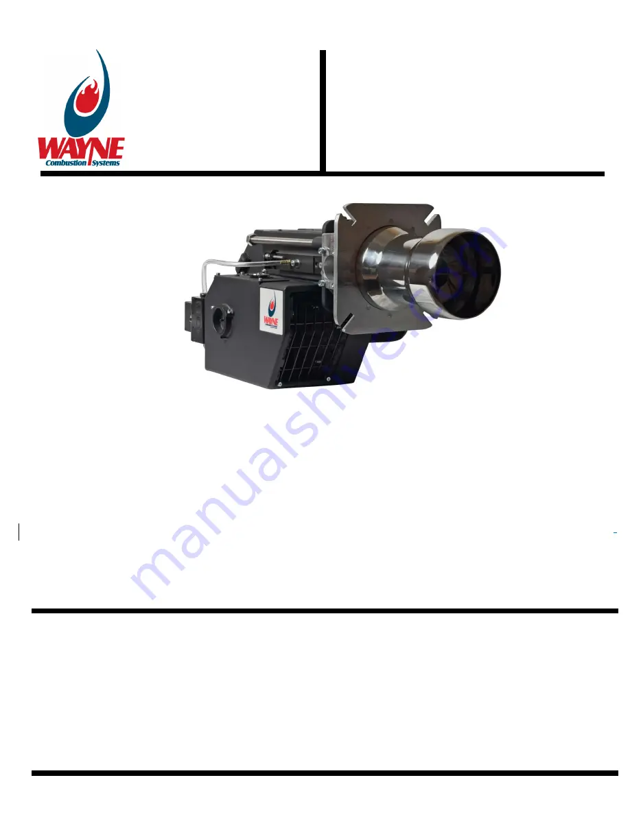
LC2300M
60,000 Btu/hr (17.5 kW)
2.3 MMBtu/hr (703 kW)
120 Vac / 60 Hz 1 Phase
Fixed Flange
6.25 inches (159 mm)
8 inches (203 mm) Maximum with
9 inch (229 mm) Air Tube
Single-Rod Ionization
UV Scanner - 1000185-SER (Optional)
)
De-rate maximum input for altitude over 2000 ft. (610 m) by 4% each 1000 ft. (305 m) above sea level.
Ignition:
6,000 Vac Direct Spark Ignition. Standard burners are shipped with the ignition transformer mounted to the burner. If the
transformer is to be remotely mounted, the ignition wire must not exceed 36” (914.4mm) per UL795.
Supply Line Pressure Required:
(see Table 1&2.)
WAYNE COMBUSTION SYSTEMS
801 GLASGOW AVE.
FORT WAYNE, IN 46803
PHONE: (260) 425-9200
(800) 443-4625
www.waynecombustion.com
LC2300M
Gas Burner
INSTALLATION OF BURNER
INSTALLATION OF THE BURNER MUST BE DONE BY A QUALIFIED INSTALLER IN ACCORDANCE WITH REGULATIONS OF
THE NATIONAL FUEL GAS CODE, NFPA 54/ANSI Z223.1, AND IN COMPLETE ACCORDANCE WITH ALL LOCAL CODES AND
AUTHORITIES HAVING JURISDICTION.
INCORRECT INSTALLATION, ADJUSTMENT, OR MISUSE OF THIS BURNER COULD RESULT IN DEATH, SEVERE
PERSONAL INJURY, OR SUBSTANTIAL PROPERTY DAMAGE AND WILL VOID THE WARRANTY.
A QUALIFIED INSTALLER IS THE PERSON WHO IS RESPONSIBLE FOR THE INSTALLATION AND ADJUSTMENT OF THE
EQUIPMENT AND WHO IS LICENSED TO INSTALL GAS-BURNING EQUIPMENT IN ACCORDANCE WITH ALL CODES AND
ORDINANCES.
THESE INSTRUCTIONS SHOULD BE AFFIXED TO THE BURNER
OR ADJACENT TO THE HEATING APPLIANCE.
Manual 63899-002 | Revision A | Publication Date: 3/20/24
Mounting Flange:
Air Tube Diameter:
Air Tube Insertions:
Flame Safety:
SPECIFICATIONS
Summary of Contents for LC2300M
Page 35: ...63899 002 Rev A 3 20 2024 35 B WIRING DIAGRAM...
Page 36: ...63899 002 Rev A 3 20 2024 36...
Page 57: ...63899 002 Rev A 3 20 2024 57...
Page 58: ...63899 002 Rev A 3 20 2024 58...
Page 59: ...63899 002 Rev A 3 20 2024 59...
Page 60: ...63899 002 Rev A 3 20 2024 60...
Page 63: ...63899 002 Rev A 3 20 2024 63 This page intentionally left blank...