


- 10 -
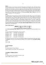
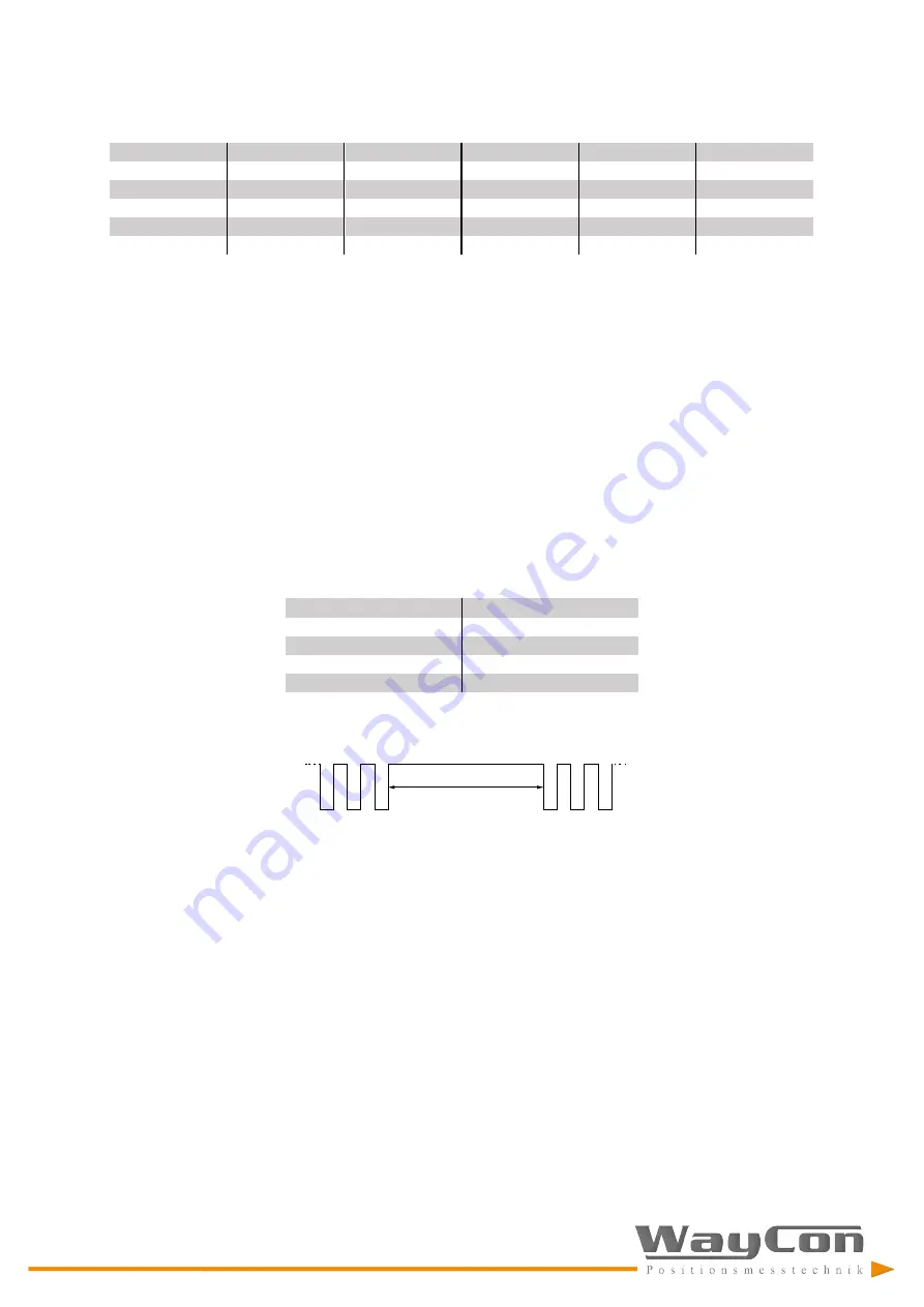
Structure of position information:
MXS2-...-50-...
bit
19
...
2
1
MXS2-...-10-...
bit
21
...
2
1
MXS2-...-5-...
bit
22
...
2
1
MXS2-...-2-...
bit
23
...
2
1
MXS2-...-1-...
bit
24
...
2
1
value
MSB
...
LSB
Error bit
NOTE:
The position value issued by the sensor is expressed in pulses. To convert the pulses into a metric
measuring unit, the number of detected pulses must be multiplied by the resolution.
Example:
MXS2-SSII-50-...
resolution = 50 µm
detected pulses = 123
position value = 50 * 123 = 6150 µm = 6.15 mm
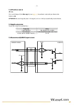
4.3 Recommended transmission rates
The SSI interface has a frequency of data transmission ranging between 100 kHz and 1 MHz.
The CLOCK signal and DATA signal comply with the “EIA standard RS-422”.
The SSI clock frequency (baud rate) depends on the length of the cable and must comply with the technical
information reported in the following table:
Cable length
Baud rate
<50 m
<400 kHz
<100 m
<300 kHz
<200 m
<200 kHz
<400 m
<100 kHz
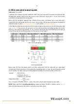
The time interval between two Clock sequence transmissions must be at least 16 µs (Tp > 16 µs).
4.4 Error bit
The error bit is intended to communicate the normal or fault status of the Slave:
“1”:
correct status (no active error)
“0”:
an error is active:
•
reading error:
The sensor is not reading the magnetic tape correctly. Among the
possible causes are: the tape is not installed properly, the magnetic
surface of the tape is damaged, the sensor is not working properly.
•
frequency error:
The sensor is travelling too fast on the tape.
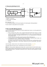
4.5 Helpful information
•
The zero-setting / Preset and Counting direction functions are not available.
•
The position information increases when the sensor moves as indicated by the arrow in figure 1,
starting from a min. value up to a max. value. Min. and max. values depend on the specific WBA2
magnetic tape installed in your application.
•
If required by your application, execute a zero-setting / Preset operation of the position read by the
Master.
Tp
Clock
Summary of Contents for MXS2
Page 1: ...Magnetic Scale MXS2 Manual...


