background image

Installing the Wavion WS-410 Metro Access Point

Installation Guide

25

3.

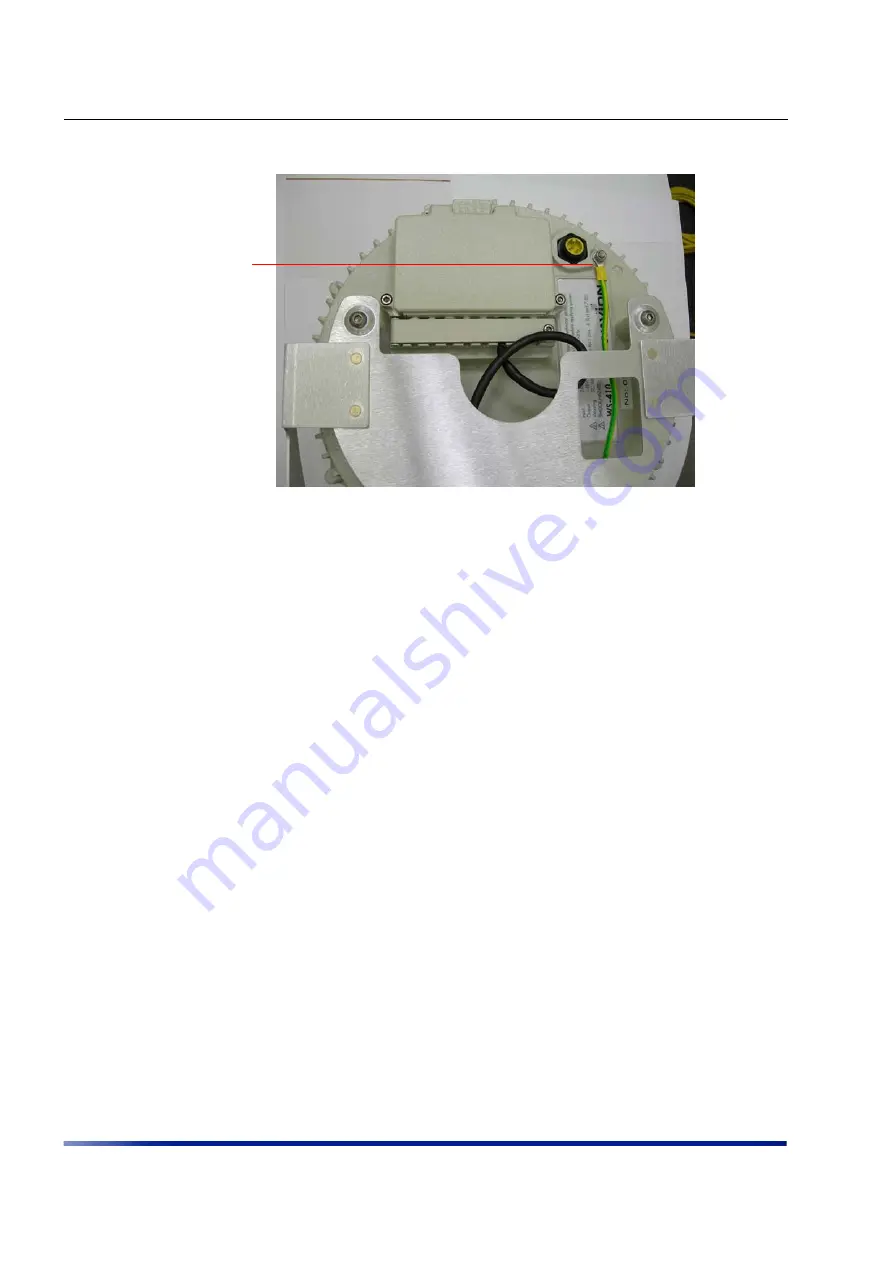
Attach #10 AWG bare copper wire with an M6 terminal ring to the grounding screw.

4.

Attach the second star washer and tighten the nut.

5.

Attach the other end of the grounding wire to a grounding strap that is attached to a 

grounded surface or other earth ground (for example, a grounding rod).

Grounding the Data Protection Device

The grounding method for an indoor data protection device is shown in 

Figure 3.15

.

To ground an indoor data protection device

1.

Position the protection device as close to the entrance of the building entrance as possible.

2.

Attach a length of #10 AWG bare copper wire to the ground post on the data protection 

device.

3.

Attach the other end of the grounding wire to the ground connection of an electrical outlet 

or a grounded water pipe.

Attach wire to

grounding

screw

Summary of Contents for WS410

Page 1: ...WS 410AD Metro Access Point Installation Guide June 2007...

Page 2: ...generates uses and can radiate radio frequency energy and if not installed and used in accordance with the instruction manual may cause harmful interference to radio communications Operation of this e...

Page 3: ...afety Precautions 13 Mounting Strategies 13 Using Hose Clamps 14 Mounting on a Pole or Streetlight 15 Metal or Wood Pole Mounting 16 Wood Brace Mounting 19 Streetlight Mounting 20 Grounding the Wavion...

Page 4: ...SN_035_EL 2 4 GHz Antenna 48 Chapter 7 INSTALLATION ACCESSORIES 53 Power Cable 54 Ethernet Cables 54 Lightning Protection 54 Power Over Ethernet 55 Client Connectivity 55 Chapter 8 AC WIRING DIAGRAMS...

Page 5: ...user to the presence of important operating and maintenance servicing instructions in the literature accompanying the product The lightning flash with an arrowhead symbol within a triangle is intended...

Page 6: ...cal Support For technical support contact Wavion using these methods Address Wavion Technical Support Wavion Inc 1190 Saratoga Avenue San Jose California 95129 USA Telephone 1 408 261 7000 Fax 1 408 2...

Page 7: ...standards based Wi Fi clients The WS410 may be mounted on streetlights or rooftops and may be easily interfaced with either wired internet connections wireless mesh or backhaul equipment Multiple pow...

Page 8: ...Introduction 8 Wavion Networks...

Page 9: ...ety Instructions on page 10 Preparing for Installation on page 11 Mounting Strategies on page 13 Using Hose Clamps on page 14 Mounting on a Pole or Streetlight on page 14 Grounding the Wavion WS 410 o...

Page 10: ...by the manufacturer CAUTION Refer all servicing to qualified service personnel Servicing is required when the apparatus has been damaged in any way For example if the power supply cord or plug is dama...

Page 11: ...ure rating to close all unfilled openings CAUTION To maintain Overvoltage Installation Category II install a suitable surge suppressor device in the branch circuit to limit expected transients to Over...

Page 12: ...s the following options for connecting to a power source AC power source 3 wire service 3W P N PE or 3W 2P PE 110 220 VAC 50 60 Hz See Chapter 7 Installation Accessories on page 53 for details NEMA pl...

Page 13: ...es and antenna clearance when choosing a mounting location The Wavion WS 410 should always be mounted with the top of the unit parallel to the ground and with the antennas pointing upward and clear of...

Page 14: ...ight Figure 3 1 Example Mounting Locations on a Streetlight Using Hose Clamps Hose clamps are used by the mounting assembly to secure the WS 410 to the mounting structure Figure 3 2 demonstrates how t...

Page 15: ...streetlight It is recommended to mount the WS 410 on aluminum or galvanized steel structures NOTE The Wavion WS 410 must be mounted with the top of the unit parallel with the ground and with the ante...

Page 16: ...pipe with diameter of 3 10 inches 2 Slip the bands of the hose clamps through the inner slots of the pole bracket Choose the slot that is appropriate for the diameter of the mast 3 Use the hose clamp...

Page 17: ...into the holes in the back plate labeled 2 in Figure 3 4 and tighten Figure 3 4 Attaching the Back Plate to the Pole Bracket 6 Attach the tray to the back plate as shown in Figure 3 5 NOTE The tray m...

Page 18: ...tighten the bolts Figure 3 5 Attaching the Tray to the Back Plate 8 Slide the WS 410 onto the tray Insert three 8mm stainless steel hex head bolts from underneath the tray into the WS 410 Use a 5mm Al...

Page 19: ...a wood brace 1 Select a mounting location 2 Attach the tray directly to the wood brace using four 5 8 inch diameter 3 inch long lag bolts as shown in Figure 3 8 Use an appropriate Allen wrench to tigh...

Page 20: ...zontal or angled arm of a streetlight To mount the Wavion WS 410 on a streetlight 1 Choose a mounting location You can attach the WS 410 to any streetlight arm with diameter of 3 to 10 inches 2 Slip t...

Page 21: ...he Back Plate to the Pole Bracket 6 Attach the tray to the back plate as shown in Figure 3 11 7 Insert four 8mm stainless steel hex head machine bolts into the tray Tighten the bolts using a 5mm Allen...

Page 22: ...nsert 3 8mm stainless steel hex head machine bolts from underneath the tray into the WS 410 and tighten the bolts Tighten the bolts using a 5mm Allen wrench Figure 3 12 Attaching the WS 410 to the Tra...

Page 23: ...the figure below Figure 3 13 Grounding Method CAUTION You must always install an external grounding wire You must also ground the outdoor data protection device to a ground rod or a bonded pipe Make...

Page 24: ...ion WS 410 Metro Access Point 24 Wavion To ground the Wavion WS 410 1 Remove the nut and star washers from the grounding screw Figure 3 14 Grounding Screw 2 Attach one star washer to the grounding scr...

Page 25: ...for example a grounding rod Grounding the Data Protection Device The grounding method for an indoor data protection device is shown in Figure 3 15 To ground an indoor data protection device 1 Positio...

Page 26: ...avion Figure 3 15 Grounding the Indoor Network Protection Unit Indoor network protection unit Data cable enters building wall through conduit To network Grounding wire to electrical outlet ground or w...

Page 27: ...he 6 antennas into the an N Type connectors on the WS 410 Figure 3 16 Connecting the Antennas The successful insertion of six antennas should look as follows WARNING Only connect the unit to the power...

Page 28: ...ge 53 for details Connecting to AC Power Category C The AC power connections for a Category C AC power source are shown in Figure 3 17 WARNING Turn the power off before working on an electrical circui...

Page 29: ...P or 2W P N 100 240 VAC 50 60 Hz See Chapter 7 Installation Accessories on page 53 for details 2 Make sure the power is turned off on the designated circuits 3 Install a 1 2 inch liquid tight conduit...

Page 30: ...essories on page 53 for details NEMA plug for streetlight photoelectric control power tap 2 wire service 2W 2P or 2W P N 100 240 VAC 50 60 Hz See Chapter 7 Installation Accessories on page 53 for deta...

Page 31: ...For outdoor lighting commonly used by utilities use the 3 prong NEMA twist lock adapter with twist lock style photoelectric controls The street light adapter uses a 3 pronged NEMA twist lock adapter t...

Page 32: ...vice 2W 2P or 2W P N 100 240 VAC 50 60 Hz See Chapter 7 Installation Accessories on page 53 for details 2 Make sure that the power is turned off on the designated circuits 3 Remove the photosensor fro...

Page 33: ...led NOTE Do not leave connectors open to the environment Cover connectors with the closure cap when not in use and tighten the cap See Chapter 7 Installation Accessories on page 53 NOTE Use only shiel...

Page 34: ...ecting to the Ethernet port if you need to terminate the Ethernet cable use a standard RJ45 termination Use a shielded RJ45 plug and be sure to connect the shield of the Ethernet cable to the shield o...

Page 35: ...crewing the two bolts 5 Open the strip next to the connector access cover by unscrewing the bolt Figure 3 21 Opening the Strip and Connector Access Cover 6 Select the slot that matches the diameter of...

Page 36: ...pply Use a shielded RJ45 8 pin modular plug to terminate the cables at the desired lengths 8 Make sure that the protection unit is properly grounded 9 Apply silicon across the rubber plugs 10 Close th...

Page 37: ...ables back to the tray and using a tie wrap to secure Connecting Peripherals The WS 410 can source DC power on the Ethernet B connector pins 4 5 and 7 8 This allows the WS 410 to power a backhaul devi...

Page 38: ...t GUI NOTE PoE can only be supported if the WS 410 is powered by AC voltage input NOTE Use only shielded Cat5e cable rated for outdoor use Chapter 7 Installation Accessories on page 53 for details For...

Page 39: ...the antennas are connected when operating the radio or attempting to transmit data otherwise the radio may be damaged Do not hold the antenna to be close to or touching any exposed parts of the body e...

Page 40: ...Installing the Wavion WS 410 Metro Access Point 40 Wavion Service Instructions The Wavion WS 410 contains no user serviceable parts inside...

Page 41: ...the operational conditions and data transmission rates The table below shows the overall maximum power consumption under different conditions WS410 Input Voltage WS410 Input Power when PoE output is n...

Page 42: ...Power Consumption 42 Wavion...

Page 43: ...2 11g OFDM 64QAM 16QAM QPSK BPSK TX Power Maximum 802 11b and 802 11g Beamformer Directed Power EIRP Beamfroming gain 42 5dBm EIRP Calculations Antenna Gain 7 5 dBi Total EIRP 3 5 dBm RX Sensitivity 8...

Page 44: ...support Configuration save and restore Network and client statistics Physical Specifications Network Interfaces Auto sensing 10 100 Ethernet Input from Wavion Injector Auxiliary Network Interface For...

Page 45: ...C For AC input see Chapter 4 Power Consumption on page 41 Output Power over Ethernet Option For powering an external device 48VDC 0 6A max 24DC 1A max Environmental Specifications Operating Temperatur...

Page 46: ...Product Specification 46 Wavion...

Page 47: ...Installation Guide 47 CHAPTER 6 Antenna Specifications and Patterns The chapter describes antenna specifications and patterns for the antennas supplied with the Wavion WS 410...

Page 48: ...the antenna Specifications Pattern 2400 2500MHz Gain 7 4dBi Length 17 5 inches Weight 4 7 oz 3dB Beam width 20 degrees Cross Polar Rejection 15dB Max Power 50 watts Max wind survival 150MPH Wind Load...

Page 49: ...Antenna Specifications and Patterns Installation Guide 49...

Page 50: ...Antenna Specifications and Patterns 50 Wavion...

Page 51: ...Antenna Specifications and Patterns Installation Guide 51...

Page 52: ...Antenna Specifications and Patterns 52 Wavion...

Page 53: ...describes the accessories available for the WS 410 and ordering information The following topics are covered in this chapter Power Cable on page 54 Ethernet Cables on page 54 Lightning Protection on...

Page 54: ...tacles An all weather cover cup for the AC power connector to be used when no AC power is required WS410CC 01 GE AA Description Manufacturer Part Number Distributor Contact Information Order Number Ou...

Page 55: ...ctor goes to pin 7 of Alvarion RJ45 connector pin 7 of the WS 410 PoE connector goes to pin 5 of the Alvarion RJ45 connector See Installation Guide Motorola Canopy Use outdoor CAT 5e cable with spare...

Page 56: ...Installation Accessories 56 Wavion...

Page 57: ...llation Guide 57 CHAPTER 8 AC Wiring Diagrams This chapter contains the following wiring diagrams for AC power AC Wiring Photoelectric Power Tap on page 58 AC Wiring Power Cable 120VAC 15A Plug on pag...

Page 58: ...ck 1 White WS410PT 02 GE AA 6 or WS410PT 01 GE AA 30 Photoelectric Power Tap Power Input Cable 2Wire 100 240VAC NEMA Plug UL Standard 773 Plug in looking type for photocontrols in use with area lighti...

Page 59: ...ire service NEMA Photoelectric Control UL773 female NEMA Photoelectric Control UL773 Power Tap Adapter male White L2 L1 L2 Protective Earth Black White WS 410 North North L1 L2 Three phase two wire se...

Page 60: ...reen Yellow White Black Green or Green Yellow WS410PC 04 GE AA 6 or WS410PC 03 GE AA 20 Overvoltage Category 2 or IEEE ANSI C62 41 Category B Power Electrical Service Cable 3Wire 120Vac Black White Gr...

Page 61: ...e Wavion WS 410 is mounted on a pole the sail area of the WS 410 is approximately 1 square foot The Wavion WS 410 can load a pole with a maximum load of 3400 Newton in wind conditions of 165mph NOTE I...

Page 62: ...Wind Loading Considerations 62 Wavion...

Page 63: ...nting equipment for the backhaul unit Make sure the WS 410 is installed in a higher position then the backhaul unit so the antennas are unobstructed If the backhaul unit is powered externally connect...

Page 64: ...Backhaul Unit Installation Instructions 64 Wavion...

Page 65: ...els Relative to an Isotropic Radiator DBPSK Differential Binary Phase Shift Keying DC Direct Current DQPSK Differential Quadrature Phase Shift Keying DSSS Direct Sequence Spread Spectrum EMC Electroma...

Page 66: ...ltiplexing P Phase PE Protective Earth PoE Power over Ethernet RJ45 Registered Jack 45 RSS Received Signal Strength Rx Receive RXD Receive Data TUV Technical Inspection Association Tx Transmit TXD Tra...

Reviews: