background image

24 

 SmartSensor HD User Guide

Installations with a pole-mount 

box and traffic cabinet

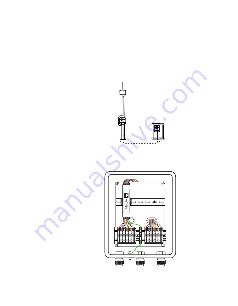
As shown below, this is an installation where the sensor cable runs 

down the pole to the pole-mount box, then down to ground level, 

where it runs underground to a traffic cabinet. Power and commu-

nication modules are located in the cabinet, and power is sent to 

the sensor via the sensor cable.

Figure 18. 

Installation with pole-mount box and traffic cabinet

Setting up the pole-mount box

Lightning

Surge

Protection

Wavetronix

Pr

ot

ec

ted

Pr

ot

ec

ted

Click!

200

RS

-485

RS

-232 DCE

To Smar

tS

ensor

GND

GND

RD

TD

CTS

RTS

GND

485+

485-

GND

-DC

+DC

To T

raffic C

abinet

GND

GND

RD

TD

CTS

RTS

GND

485+

485-

GND

-DC

+DC

Figure 19. 

Surge Preassembled Cabinet (pole-mount box)

Note.

 This section 

assumes you are 

using the Surge 

Preassembled 

Cabinet from 

Wavetronix. If you 

bought individual 

Click modules 

instead, see 

Click 

100–400 Series User 

Guide

 and support 

document 295, 

How to Assemble 

the Power Plant

. If 

you are not using 

Wavetronix devices, 

contact your 

dealer or visit the 

knowledge base at 

www.wavetronix.com.

Summary of Contents for SmartSensor HD

Page 1: ...SmartSensor HD USER GUIDE...

Page 2: ...SmartSensor HD USER GUIDE Provo Utah 801 734 7200 www wavetronix com...

Page 3: ...tised detection accuracy of the Wavetronix SmartSensor sensors is based on both external and internal testing as outlined in each product s specification document Although our sensors are very accurat...

Page 4: ...e roadway 17 Applying silicon dielectric compound 18 Connecting the cable 3 INSTALLING POWER SURGE PROTECTION AND COMMUNICATIONS 19 Installations with a pole mount box only 20 Setting up the pole moun...

Page 5: ...settings 46 Changing Outputs tab settings 48 Changing Data tab settings 6 CONFIGURING LANES 50 Alignment 51 Checking sensor alignment 52 Lane configuration 52 Capturing lanes 53 Excluding or includin...

Page 6: ...Adjusting the data interval 86 Creating adjusting and deleting speed bins 87 Creating adjusting and deleting class bins 87 Creating adjusting and deleting approaches 88 Using direction bins 88 Using...

Page 7: ......

Page 8: ...nstalling and configuring a SmartSensor HD To find the instructions for specific tasks see the table of contents If your questions aren t answered in this guide visit www wavetronix com support for ac...

Page 9: ...preassembled and prewired in pole mount boxes and cabinet backplates available from Wavetronix Service information Don t try to service or repair this unit none of its components or parts are servicea...

Page 10: ...oosing where to mount Figure 2 The HD s radar footprint The SmartSensor HD is a side fire radar detector It uses dual radar beams to get highly accurate presence speed and length data For best perform...

Page 11: ...ed and wireless options Consider timing after a vehicle passes in front of the sensor there s a slight delay before the data for that vehicle is sent from the sensor In a time sensitive application li...

Page 12: ...9 37 31 29 19 37 32 29 19 38 33 30 19 39 34 30 19 39 35 30 20 40 36 30 20 41 37 31 20 41 38 31 21 42 39 33 21 43 40 33 22 43 41 34 22 44 42 34 22 44 43 35 22 45 44 35 23 46 45 36 23 46 46 36 23 47 47...

Page 13: ...is frequently used by tall vehicles consider choosing a higher mounting height to help avoid occlusion Don t use an offset of less than 6 ft 1 8 m Also the sensor can be up to 230 ft 70 1 m from the r...

Page 14: ...trucks Signs Barriers and sounding walls Trees and more Normal detection Signal that doesn t return to sensor is scattered Signal bouncing off wall causes false detection Figure 5 Left direct path ret...

Page 15: ...be sure to give the two sensors a 70 ft 21 3 m lateral offset and put them on different RF channels Put two sensors on the same pole in the middle of the median both pointing out put them on different...

Page 16: ...r Figure 6 Mounting the sensor 1 Prepare the sensor while still on the ground remove the large bolts holding the end knuckle to the mount then use the four small bolts and lock washers to attach the k...

Page 17: ...pointed down Don t tighten completely yet as you still need to align the sensor to the roadway Aligning the sensor to the roadway Figure 7 Up and down positioning 1 Tilt the sensor down so the front i...

Page 18: ...matches the grade of the road this will require the purchase of a rotating sensor backplate 4 Once you are satisfied with the sensor alignment and position ing tighten all bolts in the mount Applying...

Page 19: ...ate a drip loop as shown above and gives you something to work with should you someday need to move the sensor to a different spot on the pole 4 If there s excess cable don t cut it as you may need it...

Page 20: ...pole to the pole mount box and to nowhere else Power comes from solar a battery or a power line that runs straight to the pole communications are wireless or use a comms line that runs straight to th...

Page 21: ...that were included in the package and attach them to the back of the Standard Preassembled Cabinet 2 Use Band It or a similar clamping system to attach the Standard Preassembled Cabinet to the pole No...

Page 22: ...ftmost cable grip on the bottom of the box Twist the cable grip to tighten 4 Insert the black conductor into the round hole on the plug por tion of the L terminal block do not strip the insulation Ins...

Page 23: ...cable to terminal blocks 6 Insert the sensor cable the pigtail cable coming from the sensor into the middle grip on the bottom of the box Twist the cable grip to tighten 7 Follow the instructions in s...

Page 24: ...C converter The Click 200 which is a lightning surge protector This device is where the sensor cable is landed via the terminal blocks It protects the rest of the pole mount box from surges coming fro...

Page 25: ...inet Setting up the pole mount box Lightning Surge Protection Wavetronix Protected Protected Click 200 RS 485 RS 232 DCE To SmartSensor GND GND RD TD CTS RTS GND 485 485 GND DC DC To Traffic Cabinet G...

Page 26: ...affic Cabinet GND GND RD TD CTS RTS GND 485 485 GND DC DC GND GND RD TD CTS RTS GND 485 485 GND DC DC Figure 21 Connecting sensor cable to terminal blocks 3 Insert the sensor cable the pigtail cable c...

Page 27: ...nd of the homerun sensor cable the cable that runs to the traffic cabinet into the leftmost grip on the bottom of the box Twist the cable grip to tighten 7 Follow the instructions in steps 4 and 5 to...

Page 28: ...ate for traffic cabinet Lightning Surge Protection Wavetronix Protected Protected Click 200 RS 485 RS 232 DCE 110 VAC SmartSensor GND GND RD TD CTS RTS GND 485 485 GND DC DC L N G Figure 25 Mounting t...

Page 29: ...om Wavetronix with the conductors in the cable already ter minated in a terminal block plug Insert this plug into the power terminal blocks 4 If for some reason the conductors aren t terminated into t...

Page 30: ...lant consisting of a circuit breaker AC surge protector and AC to DC converter located in the traffic cabinet Two Click 200 modules which are lightning surge protectors one at either end of the underg...

Page 31: ...ou config ure and interact with the HD sensor It can only be installed on a PC Downloading SSMHD Figure 28 Finding the SSMHD download on the Wavetronix website 1 In a browser navigate to www wavetroni...

Page 32: ...1 Double click on the setup file 2 Follow the instructions on your screen to choose where to install and then to choose which shortcuts to create 3 Click Finish when you re done SSMHD main screen Open...

Page 33: ...OK Changing the software size Click one of the three boxes at the bottom of the screen to choose between the small medium and large display sizes SSMHD communication basics Figure 32 Connect button m...

Page 34: ...his to Hardware if you re connecting through a device that uses RS 232 hardware handshaking some older devices require flow control handshaking because they cannot keep up with the data rates of highe...

Page 35: ...e software tries to connect to the sensor before it gives up You can increase this time if you re having trouble connecting to the sensor Installation Type If there is only one sensor connected to the...

Page 36: ...mulated traffic use the three set tings under Traffic Properties to change the style flow and average speed of the traffic 4 Click Connect About virtual sensor files If you make changes to the sensor...

Page 37: ...port wavetronix com Advanced communication tools Once you ve made a connection the Connect button of the main screen should now be animated with arrows moving past each other and it should now say Con...

Page 38: ...and delete device connection settings Viewing the error log Figure 38 Error log 1 Click on the notepad icon at the bottom of the connection screen serial Internet or virtual 2 The error log will be sa...

Page 39: ...ct the sensor 3 Enter the new password into the Password field 4 Click OK If you forget your password Figure 40 Forgotten Password window When you re prompted to enter the password you ll see a link y...

Page 40: ...ntrol screen will appear 2 If you would like specifics on the mismatch click the Details button 3 Click Install Upgrade or if you prefer not to upgrade at this time click Close Reading the date code 2...

Page 41: ...owngrading the sensor Figure 43 Downgrade warning message If the downgrade message appears it means that the sensor firm ware is newer than the version of SSMHD you re using Get the newest version of...

Page 42: ...5 Configuring Sensor Settings Figure 44 Settings button main screen Access the sensor settings by clicking Settings on the main screen Changing these settings is optional if you leave them set to thei...

Page 43: ...ts of the sensor serial number No two sensors should have the same ID Subnet change if you want to create groupings of sensors ID generally you won t need to change this Description Lets you create a...

Page 44: ...standard mph feet metric kph meters or UK mph meters Purely for your convenience does not affect sensor performance Date Time Shows the date and time stored on the sensor s internal clock The sensor s...

Page 45: ...default to 9600 bps Response Delay Lets you set how long the sensor will wait before responding to a received message shown in milliseconds Default is 10 ms Change this if you re using a communicatio...

Page 46: ...ix devices default to 9600 bps Response Delay Lets you set how long the sensor will wait before responding to a received message shown in milliseconds Default is 10 ms Change this if you re using a co...

Page 47: ...the traffic data it reports Choose Antenna for standard use reports data as detected by the sensor Choose Diagnostic for testing and training creates simulated traffic RF Channel Lets you change whic...

Page 48: ...ox if your backend system was originally configured for a SmartSensor 105 and is still expecting data in SS105 protocol RTMS X3 Sets the sensor to use the RTMS communication protocol although only a p...

Page 49: ...ettings Figure 48 Data tab Setting Description Details Max Vehicle Length Lets you set your maximum vehicle length any detected vehicle that exceeds this length is reported as being only this long Cha...

Page 50: ...onfiguring Lanes 49 6 Configuring Lanes Figure 49 Lanes button main screen Click the Lanes button on the main screen to open the Lanes screen then click the Configuration button to open the Configura...

Page 51: ...50 SmartSensor HD User Guide Figure 50 Lanes screen Alignment Sidebar Sidebar button View menu Alignment arrow Figure 51 Alignment tools...

Page 52: ...x it Give the software a few moments after each sensor movement to adjust a few vehicles need to pass by before it can report on the new alignment 6 If you d like hide the arrow again using the View m...

Page 53: ...nes as inactive or excluded covered in the next section until the alignment is taken care of Lane configuration Sidebar Sidebar button View menu Tools menu Roadway Shoulder area Figure 54 Configuratio...

Page 54: ...to capture all the lanes that appear in the sidebar click anywhere in the sidebar in the Automatic Lane window that appears click Copy Sidebar If you only want to capture certain lanes click on those...

Page 55: ...e a blue automatically configured lane Editing a lane name Figure 58 Lane window 1 Click on the lane you want to edit The Lane window will appear 2 Change the Name field at the top Note Other options...

Page 56: ...will save the configuration Click OK Click on the gray dot under the sensor for a shortcut to the Ver ification screen Either of these will cause a prompt to appear asking if you want to save Click Y...

Page 57: ...ions Setting Description Details off No sidebar shown N A 1 Automatic configuration Shows the lanes that have been automatically detected by the sensor in blue Use this to save only certain automatica...

Page 58: ...larger the arrow shaped indicators become For best results you ll need to let this run for a few minutes Use this to get a sense of where vehicles are most often being detected which can be useful fo...

Page 59: ...changed Copy Lane Saves the lane you clicked on to the edit area An automatic lane will appear blue a saved lane turns black Copy Sidebar Saves all the lanes currently shown in the sidebar to the edi...

Page 60: ...ation is open click on one of the lanes in the sidebar to open this window Setting Description Details Direction Shows the direction of traffic as it s been detected by the sensor Can t be changed her...

Page 61: ...gured lanes to your configuration Sidebar 2 shoulder area window If you click the shoulder area instead of a lane it will open a window with just the range width of the shoulder and the Copy Sidebar o...

Page 62: ...cle s speed its length or the length class bin it falls into class will be grayed out if no class bins are currently configured learn how to configure them in chapter 8 Speed is the default If you re...

Page 63: ...Last Edit Undoes the last edit undertaken in the edit area N A Clear Edit Area Clears all captured and manually created lanes from the edit area Does not clear automatically configured lanes however A...

Page 64: ...D with a new one and don t want to do the whole configuration process again You can save from the old sensor put up the new one and load it with the lane information Restart Auto Cfg Begins the automa...

Page 65: ...the process of saving only a portion of the automatically configured lanes see the Lane Configuration section of this chapter for details Hiding automatic lanes can also be done through the Automatic...

Page 66: ...nge that setting this will default to north You can change the orientation by clicking on the compass This setting is for your information and doesn t affect sensor operation Show Hide Alignment Shows...

Page 67: ...on to the sensor s configuration When captured the lane will turn from blue to black This can also be done by clicking on the automatic configuration sidebar Exclude Tells the sensor to ignore the la...

Page 68: ...er of the name with LANE_01 nearest the sensor When you add a new lane all lanes with this name format will be updated For RTMS and Z4 data push lane mapping may be changed using the notation xx xx be...

Page 69: ...ction Protection a setting found on the Verification screen will be disabled Choose Left or Right depending on the direction the traffic is moving If Direction Protection is turned on then choosing Le...

Page 70: ...emporarily disappear or to be ignored consider excluding or deactivating the lane instead this will make it possible to easily recover the lane without having to reconfigure it Exclude Tells the senso...

Page 71: ...and placement of the lanes Range refers to the distance from the sensor Can t be changed Hide Auto Lanes Hides but does not delete the automatically configured lanes from the edit area This can also b...

Page 72: ...ignment or configuration To include the area again click it to open the Excluded Area window and click Include This may be useful in order to ignore phantom detections from multipathing An excluded ar...

Page 73: ...sor Change these values with the arrows or by typing in order to manually fine tune your lane placement Be aware that changing these may cause other lanes to change size or even disappear Include Area...

Page 74: ...7 Verifying Lanes 73 7 Verifying Lanes Figure 70 Lanes button main screen Click the Lanes button on the main screen to open the Lanes screen then click the Verification button to open the Verification...

Page 75: ...cle Display menu Vehicle Display menu Figure 72 Lane verification tools Verifying lanes means comparing the detection data in the SSMHD software with the actual traffic in the roadway you can observe...

Page 76: ...hanging the mounting locations If all else fails contact your dealer or support wavetronix com Verifying lanes using sidebars 1 Set up a way to observe on road traffic seat yourself in a place where y...

Page 77: ...ed on the roadway It s easiest to do this one lane at a time For instance you could manually count all vehicles that pass in lane 1 in a set period of time then check to see if the volume counts match...

Page 78: ...place where you can see both the road and the computer or have someone else observe traffic for you while you monitor your computer 2 Click on the paper icon to open the Per Vehicle Data screen This w...

Page 79: ...use button will cause the screen to stop being updated when you hit play again it will resume The stop button will also stop the screen from being updated but when you hit play all previous detections...

Page 80: ...your computer C ProgramFiles Wavetronix SmartSensor Manager HD vX X X bin The file that was created will be a csv spreadsheet that can be opened in Microsoft Excel 7 Compare the logged data to what w...

Page 81: ...the top of the screen all lanes will be automat ically selected Now use the slider number field and or Default button to make desired changes 5 Click OK Setting Description Details Volume Adjusts the...

Page 82: ...tently too high or too low After you enter a value the sensor calculates the speed of each detection and then multiplies it by your entered value Length Increases or decreases the length calculated fo...

Page 83: ...cles with trailers Increasing the extension time will help make sure such vehicles aren t counted as multiple detections but too much can lead to multiple vehicles being detected as a single vehicle A...

Page 84: ...counted By default Direction Protection is turned on for each lane although if you set a lane as bi directional this setting is turned off and can t be turned back on from here you ll have to go back...

Page 85: ...84 SmartSensor HD User Guide 8 Setting Up and Downloading Sensor Data Figure 76 Data button main screen Click the Data button on the main screen to open the Data screen...

Page 86: ...creen lets you define interval length bins class speed and direction and approaches You can set all some or none of these definitions simultaneously How you set these will affect your sensor s onboard...

Page 87: ...The number that you see is the maximum speed for that bin For instance in the image above the highlighted bin is for vehicles traveling between 66 and 85 miles per hour 3 To delete a bin highlight it...

Page 88: ...he Name field at the top 3 From the lanes list on the left select a lane you want in your new approach 4 Click the right arrow to move it to the approach list on the right 5 Repeat for all desired lan...

Page 89: ...ns screen Using the Speed 0 option If during an interval the volume is zero meaning no cars were detected SSMHD will report the average speed of the last good interval If you would like the intervals...

Page 90: ...n done 4 Click the checkboxes of what you want to log Lanes Approaches or both If you don t click either checkbox the resulting log file will be blank 5 To begin logging click the switch icon When you...

Page 91: ...verage speed See chapter 7 for more details 85 85th percentile speed meaning that 85 of the vehicles in the interval were going this speed or slower Headway Average time separation between vehicles in...

Page 92: ...r data storage covers Newest Shows the timestamp of when the most recent interval data packet was stored Use this to see what timeframe your data storage covers Total Shows the amount of time that dat...

Page 93: ...packets and therefore you can leave the sensor alone for longer periods between your data downloads Always check back to this screen after you have changed all other settings to get the most accurate...

Page 94: ...in and End fields editable Set those to the desired begin and end date times for your download 3 Click Start Download Figure 87 Download Progress 4 The Download Progress window will appear to show the...

Page 95: ...ata covers 6 There are three formats you can view or export the downloads in a comma delimited csv file a Microsoft Excel file or a Wavetronix specific text format that opens in a text editor like Not...

Page 96: ...click on the corresponding tab Event Interval or Presence 2 Click the Enabled checkbox 3 Choose which port you want to push the data on RS 485 or RS 232 Be aware that both of these are half duplex me...

Page 97: ...in the Loop Emulation settings Use this when you re using the SmartSensor HD in a system that was designed for dual inductive loops Z4 1 Loop Emulates a single loop system Duration is measured using...

Page 98: ...Emulates the interval data from older versions of this sensor it s similar to the HD format but lacks speed bins and direction bins and has fewer length bins Use this when you re using a newer SmartS...

Page 99: ...he Z4 format it s a 24 bit address Make sure this destination address is unique for the communications bus in use 6 If you d rather just broadcast the pushed data click the Broad cast checkbox to push...

Page 100: ...Chapter 9 Using Tools 99 9 Using Tools Figure 90 Tools button main screen Click the Tools button on the main screen to open the Tools screen...

Page 101: ...100 SmartSensor HD User Guide Figure 91 Tools screen Backing up and restoring sensor setup files Figure 92 Backup Restore screen...

Page 102: ...necessary Alternatively it may be useful if you are replacing a sensor in the field and you want to quickly apply the settings from the old sensor to the new one Restore File Loads a backup file ssc t...

Page 103: ...e the sensor was licensed N A Feature Shows a list of all possible sensor features along with its status whether or not it is enabled under the current license or for variable features such as number...

Page 104: ...amp of the last time the sensor powered up or down May be useful for diagnostic purposes to see if the sensor has lost power at some point Reboot Shows the timestamp of the last time the sensor was re...

Page 105: ......

Page 106: ...ication See Ethernet See RS 232 See RS 485 device 19 23 29 in SSMHD 32 40 Configuration screen Lanes 49 72 contact closure device 8 47 96 97 converter AC to DC 8 23 29 D data definitions See Definitio...

Page 107: ...tation 43 65 Outputs tab Settings 46 overpass 14 P password 38 per vehicle data 74 77 78 87 pole 10 11 14 15 18 19 20 24 25 pole mount box See Standard Preassembled Cabi net See Surge Preassembled Cab...

Page 108: ...29 terminal server 34 36 termination 44 thresholds 14 75 76 78 79 81 time 43 timeout 33 34 Tools screen 99 103 traffic cabinet 10 24 29 trees 10 13 troubleshooting 36 37 51 tunnels 14 turn lanes 9 U u...

Page 109: ...www wavetronix com...

Reviews: