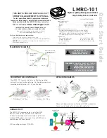
LMRC-101
Digital Lighting Management (DLM)
Single Relay Room Controller
Quick Start GuideQuick Start Guide
Room
Controller
J Box
Corner Mount
Occupancy
Sensor
Switch
To
Load/Line
(Class 1 wiring)
DLM Local Network
(low voltage, Class 2)
LMRJ Cables
PLACEMENT EXAMPLE
CONNECTIVITY
The LMRC-101 communicates to all other DLM
devices connected to the DLM Local Network.
Connection drawings are for example only. The low
voltage LMRJ cables can connect to any DLM device
with an open RJ45 receptacle.
All line voltage wiring is #12 AWG.
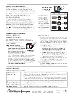
Line
Voltage
Room
Controller
J-Box
Daylight Sensor
Switch
Ceiling Mount
Sensor
DLM Local Network
Low Voltage
LMRJ Cables
Load
Line/Hot
Black wire
Neutral
White wire
Red wire
to Load
LMRC
101
Switch
ATTACHING CABLES
MOUNTING THE CONTROLLER
The LMRC-101 room controller can either be mounted
external to a junction box, placing it in the plenum space or
mounted directly inside a 4” x 4” junction box.
Outside a 4” x 4” box Inside a 4” x 4” box
Remove rubber jack covers if using all 3 RJ45 receptacles.
Leave covers in place for all unused receptacles.
Input Voltage:. . . . . . . . . . . . . . . . . . . . . . . .120/230/277VAC, 50/60Hz
Load Requirements:
Incandescent . . . . . . . . . . . . . . . . . . . . . . . . . . . . . . 20A @ 120VAC
Ballast. . . . . . . . . . . . . . . . . . . . . . . . . . . . . . . . .20A @ 120/277VAC
Motor. . . . . . . . . . . . . . . . . . . . . . . . . . . . . . . . . 1Hp @ 120/240VAC
Output . . . . . . . . . . . . . . . . . . . . . . . . . . . . . . . . . . . .150mA @ 24VDC
DLM Local Network Characteristics:
Provides low voltage power over Cat 5e cable (LMRJ).
Supports up to 24 communicating devices, including 4
LMRC-10x or LMPL-101 max per each DLM Local Network.
Free topology up to 1,000ft of low voltage cable.
Environment:
Operating Temperature. . . . . . . . . . . . . .32° to 104°F (0° to 40°C)
Storage Temperature . . . . . . . . . . . . . . 23° to 176°F (-5° to 80°C)
Relative Humidity. . . . . . . . . . . . . . . . . 5 to 95% (non condensing)
Patent Pending
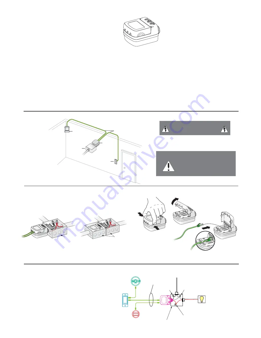
Line
J-Box
Load
J-Box
Load
Line
WARNING:
TO CONNECT A COMPUTER TO THE DLM
LOCAL NETWORK USE THE LMCI-100.
NEVER CONNECT THE DLM LOCAL
NETWORK TO AN ETHERNET PORT
–
IT MAY DAMAGE COMPUTERS AND
OTHER CONNECTED EQUIPMENT.
CAUTION:
TURN THE
POWER OFF AT THE CIRCUIT
BREAKER BEFORE WIRING.
THIS UNIT IS PRE-SET FOR PLUG n’ GO™
OPERATION, ADJUSTMENT IS OPTIONAL.
For full operational details, adjustment and more
features of the product, see the DLM System Installation
Guide provided with the LMRC-102 room controller,
and also available at
www.wattstopper.com
INSTALLATION SHALL BE IN ACCORDANCE WITH ALL
APPLICABLE REGULATIONS, LOCAL AND NEC CODES.
Wire connections shall be rated suitable for the wire
size (lead and building wiring) employed.
For Class 2 DLM devices and device wiring:
To be connected to a Class 2 power source only.
Do not reclassify and install as Class 1, or Power and Lighting Wiring.
WARNING:
Do not install to cover a junction box having Class 1, 3 or
Power and Lighting Circuits.


