Element
Section 3: Installation
L-OMM-0003_A
• 10/8/2021 Technical Support • (800) 526-0288 • Mon-Fri, 8 am - 5 pm EST Page
20
of
157
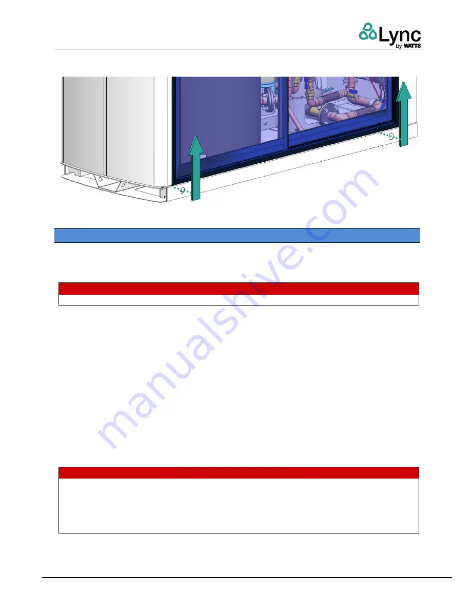
Moving the Unit with Crossbars:
Insert crossbars through the entire width of the unit. Hole
diameter is 1.5in (3.8cm). The width of Element is 35.5in (90.2cm).
Figure 7
– Crossbar Insertion Points
3.4 Site Selection and Preparation
No concrete pad is required for installation of the Element. Ensure that the site selected includes
the following:
•
Access to AC Input Power: 120 VAC, Single-Phase, 60 Hz @ 30 Amps
W A R N I N G :
Always follow local codes and regulations to reduce risk of electrical shock.
•
Access to a natural gas line or LP gas (propane) line.
o
Natural gas units require a minimum flowing pressure of 3.5 inches of water
column (0.87 kPa) with the unit operating at maximum BTU output. Maximum static
pressure is 14.0 inches of water column (3.49 kPa).
o
LP gas units require minimum flowing pressure of 8.0 inches of water column (2.0
kPa) with the unit operating at maximum BTU output. Maximum static pressure is
13.0 inches of water column (3.24 kPa).
•
A cold-water connection protected by a backflow prevention assembly per local codes.
•
Access to the internet via RJ45 connection. Ensure any firewalls, IP filters, and MAC filters
are appropriately configured.
•
Floor drain, for condensate and water discharge. Maximum water discharge is from a fully
open 1” CTS pipe at system return pressure. Discharge to floor drain shall pass through
an air gap per local codes.
W A R N I N G :
Condensate discharge from the Element can be corrosive and damage the drain, waste, vent
(DWV) piping system. It is recommended to install a condensate neutralizer such as the Lync
CN-2 between the Element condensate drain tube and discharge to drain.
Risk of flooding if floor drain is not sized or located properly. Risk of excessive splashing from
a drain grate can create a slip and fall hazard.


