AM Series Pool Heater User Manual
SECTION 5: INSTALLATION
– PIPING
OMM-0111_B:
•
GF-146-P
•
10/29/2019
Technical Support
•
(800) 526-0288
•
Mon-Fri, 8 am - 5 pm EST Page 28 of 47
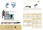
Figure 5-3: Condensate Tank Draining
A condensate removal pump is required if the boiler is below the drain. When installing a condensate
pump, select one approved for use with condensing boilers and furnaces. The pump should have an
overflow switch to prevent property damage from condensate spillage.
5.7 Pool Water Piping Requirements
Pool water piping must be field constructed of materials as specified. Piping must have individually
isolating shutoff valves installed by the installing contractor for service and maintenance.
5.8 Pool Water Connections to the Heat Exchanger
The supply and return water piping connection size to the indirect heat exchanger is 1-1/2" NPT
for models AM 399P/500P and 2" NPT for models AM 750P / 1000P.
The connections of the indirect heat exchanger to the Pool / spa water piping connections is 3"
NPT for models AM 399P/500P and 3" Flg for models AM 750P / 1000P.
Attaching Pool Water Connections to Heat Exchanger
Pool water is designed to flow from left to right of when viewed from the rear of the boiler. A
factory-wired return sensor is supplied with the pool heater; this is a strap-on type sensor and
must be field installed onto the near the pool water inlet side of the heat exchanger.
Figure 5-4: Heat Exchanger Connections and Flow Direction
WATER RETURN
TEMPERATURE
SENSOR
INLET
OUTLET
E
= Condensate Drain Pipe
F
= Floor Drain or Drain Pan
E
F


