IS-15M2
Water Hammer Arrestors
Sizes:
1
⁄
2
" – 1" (15 – 25mm)
Available in All PDI Unit Sizes A – F
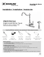
Fig. 1
Shock
Source
Fig. 2
Shock
Source
May be Installed in
a Horizontal Position
Sizes:
1
⁄
2
" NPT - SIZE A 15mm
3
⁄
4
" NPT - SIZE B 20mm
1" NPT - SIZE C 25mm
1" NPT - SIZE D 25mm
1" NPT - SIZE E 25mm
1" NPT - SIZE F 25mm
Sizes:
1
⁄
2
" Solder - SIZE A 15mm
3
⁄
4
" Solder - SIZE B 20mm
1" Solder - SIZE C 25mm
1" Solder - SIZE D 25mm
1" Solder - SIZE E 25mm
1" Solder - SIZE F 25mm
Series 15M2 and LF15M2
WARNING
!
Read this Manual BEFORE using this equipment.
Failure to read and follow all safety and use information can
result in death, serious personal injury, property damage, or
damage to the equipment.
Keep this Manual for future reference.
1. Install as close to shock source as possible.
2. Install a shock arrestor on both hot and cold lines.
3. Best results are obtained when installed as shown in Figure 1
or Figure 2. They can be installed in concealed locations with-
out access panels.
Operating Pressure
Designed to operate on all domestic and commercial lines at
150psi (10.3 bar) working pressure. Systems which exceed
60psi (414 kPa) shall be installed with a pressure reducing valve
upstream of the unit.
Temperature Range
33°F to 180°F (0.5°C to 82°C)
Installation
May be installed in new or existing plumbing systems with a stan-
dard pipe tee vertically, horizontally or at any angle. Series 15M2
and LF15M2 are factory air charged and permanently sealed. They
may be installed in concealed locations without access panels and
are not rechargeable in the field.
Standards
A.S.S.E. 1010 Approved
ANSI A112.26.1M Approved
Listed by UPC
P.D.I. WH201 Approved & Certified
Installation