

5-3/8" [137]
12" [305]
4" [101]
APPROX.
A
1-7/16" [37] MIN.
2-7/16" [62] MAX.
WALL
1/2" [13]
TUB RIM
1/2-14" NPT
MALE INLET
ALL DOTTED LINE PIPING SUPPLIED BY OTHERS.
1/2" COPPER
SLIP JOINT
CONNECTION
3-1/4" [82]
5" [127]
4-5/8" [118] DIA
ROUGH-IN
GUIDE
1/2" IPS CONNECTIONS
OR
1/2" COPPER SWEAT
CONNECTIONS
NOTE:
'T' TO BE
ON BOTTOM
AS SHOWN
78" [1981 ]
APPROX.
TO FINISHED
FLOOR
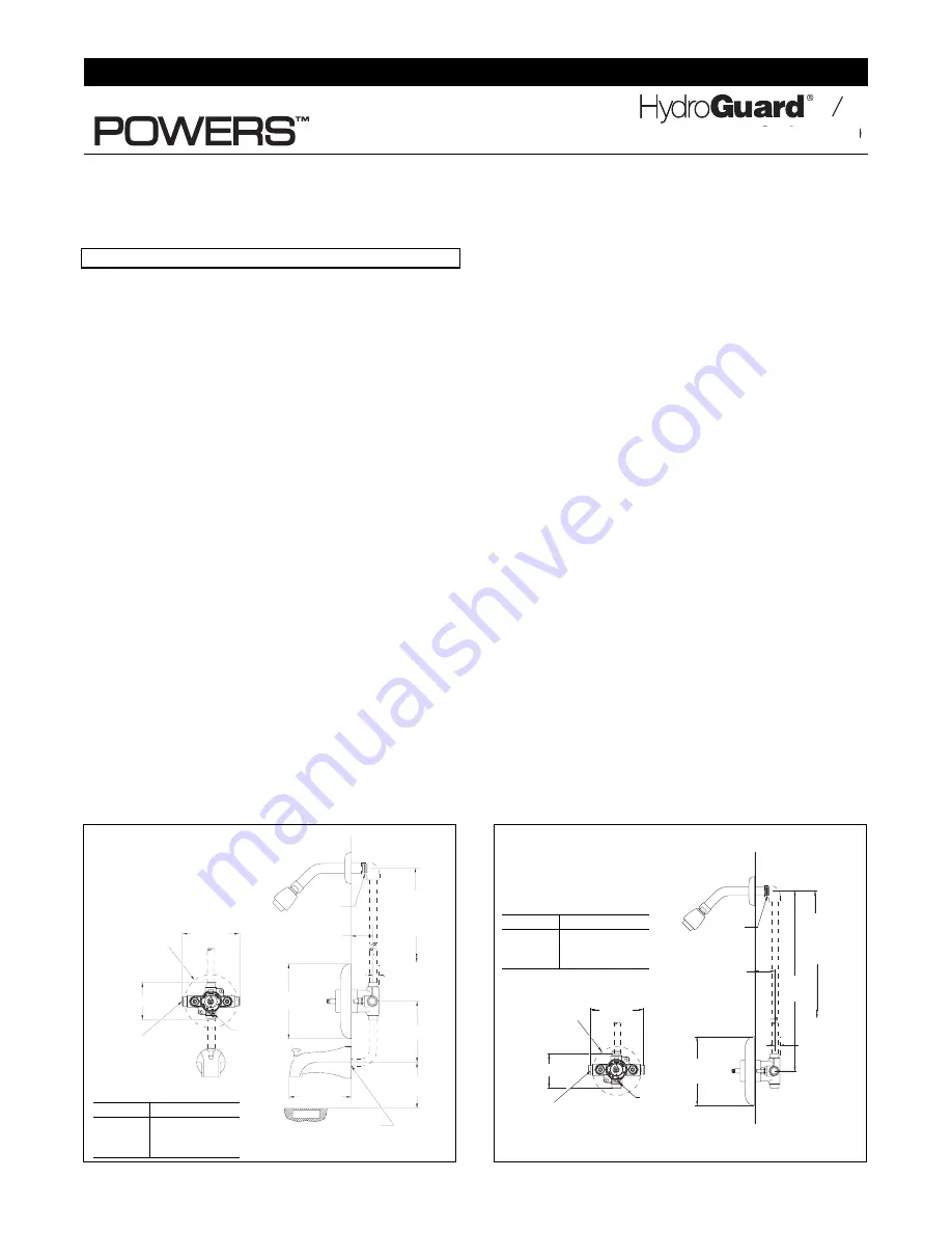
Figure 1: Rough-in Dimensions —
Tub and Shower
TUB OUTLET
TUB OUTLET
TO BE PLUGGED.
TO BE PLUGGED.
PLUG BY OTHERS.
PLUG BY OTHERS.
5" [127]
5" [127]
A
24" [609]
24" [609]
APPROX.
APPROX.
WALL
WALL
1-7/16" [37] MIN.
1-7/16" [37] MIN.
2-7/16" [62] MAX.
2-7/16" [62] MAX.
1/2" [13]
1/2" [13]
1/2" IPS CONNECTIONS
1/2" IPS CONNECTIONS
OR
OR
1/2" COPPER SWEAT
1/2" COPPER SWEAT
CONNECTIONS
CONNECTIONS
1/2-14" NPT
1/2-14" NPT
MALE INLET
MALE INLET
ALL DOTTED LINE PIPING SUPPLIED BY OTHERS.
ALL DOTTED LINE PIPING SUPPLIED BY OTHERS.
78" [1981]
78" [1981]
APPROX.
APPROX.
TO FINISHED
TO FINISHED
FLOOR
FLOOR
4-5/8" [118] DIA
4-5/8" [118] DIA
ROUGH-IN
ROUGH-IN
GUIDE
GUIDE
NOTE:
NOTE:
'T' TO BE
'T' TO BE
ON BOTTOM
ON BOTTOM
AS SHOWN
AS SHOWN
3-1/4" [82]
3-1/4" [82]
Figure 2: Rough-in Dimensions —
Shower only
Dimensions in inches [millimeters]
T P
INSTALLATION INSTRUCTIONS
Note: Installation should be in accordance with accepted
plumbing practices. Flush all piping thoroughly before
installation.
TO INSTALL
1. Position mixer 1-15/16
″
± 1/2
″
[49mm ± 13mm] from inlet
center to finished wall surface. The tub outlet port is
marked “TUB” and should face down. Facing front of
mixer, connect hot water to left side and connect cold
water to right side. The valve has “C” and “H” cast into the
body near the appropriate inlet ports.
2. Valve is factory-set for standard inlets. If
reversed inlets
are required due to back-to-back installation (Cold water
supply on the left and Hot water supply on the right), follow
instructions a–d below:
a. Connect
cold inlet
to
hot port
(“H”) and
hot inlet
to
cold port
(“C”).
Note:
Do not turn valve upside down. If
valve is upside down, water will not flow properly
through tub spout or showerhead.
b. Turn water off with checkstops, remove bonnet and car-
tridge.
c. Reinstall cartridge. “H” on the cold side of the valve
body and “C” should be on the hot side of the valve
body.
d. Reinstall bonnet with high temperature limit stop on it.
Note: Be certain that valve opens in full cold!
e. Hot and Cold inlets should be re-identified for reversed
inlets to avoid confusion during future maintenance.
3. For
tub and shower installations,
see Figure 1. Pipe bot-
tom outlet port “TUB” directly to the diverter tub spout. The
mixer body is designed to operate without the use of a twin
ell. Pipe top outlet port “S” to the showerhead.
4. For
shower only installation,
see Figure 2. Pipe top outlet
port “S” directly to the showerhead and plug bottom port.
5. Rough-in guide installation…
a. When piping installation is completed and before doing
the finished wall, slide rough-in guide onto the mixer
stem and press fit into place. (See Figure 4.)
b. The rough-in guide will insure the proper size opening for
mixer and checkstop shut-off and repair accessibility, as
well as protect the chrome-plated sleeve from damage
during drywall and tile installation.
6. To install dial gaskets, peel backing off gaskets and attach
gaskets to inside of dial plate.
6. (a)
For e707
Attach indicator plate gasket to the back of the trim plate
making sure horizontal holes on the gasket matches hor-
izontal holes on the trim plate. Indicator plate locator
hole matches diagonal hole on the trim plate. Peel off
backing of the trim plate gasket and attach to the inside
top edge of the trim plate. Gasket should be approxi-
mately 1/16" beyond the plate edge.
7. (a)
For e705 & e710
After wall is completed, remove rough-in guide. Install O-
ring on the bonnet. Slide sleeve on the bonnet and attach
dial assembly and handle to mixer body with the screws
furnished.
7 (b)
For e707
1. Install trim plate.
2. Snap on the indicator plate. Guide on the back of the
plate goes into the locator hole.
3. Install sleeve O-ring on the bonnet. Slide sleeve on the
bonnet.
CAUTION:
Indicator plate must be installed before sleeve.
4. Install handle and tighten the setscrew.
CAUTION:
When soldering during installation process, do not
heat the valve any higher than the temperature required to flow
solder. Excessive overheating of the valve may cause damage
to the cartridge mechanism.
By following this recommenda-
tion, you will be able to solder the valve without removing
either the cartridge or the checkstop internals.
If either
brazing or resistance (electric) solder is to be used, all valve
internals must be removed.
8. Maximum temperature setting adjustment (see Figure 5)
must be set on the job to in no case greater than 110°F
[43°C]. The high temperature limit stop is located on the
bonnet. Rotate handle to the maximum desired outlet tem-
perature. With an open-end wrench, screw high tempera-
ture limit stop into bonnet until it touches stem’s shoulder.
Close valve and open it to full hot to verify settings.
Model #
"A"
e705
6.5" 165mm
e707
8.5" 216mm
e710
6.5" 165mm
Model #
"A"
e705
6.5" 165mm
e707
8.5" 216mm
e710
6.5" 165mm
IIe700
Series e700


