


12
Pat. Pend.
Double Pole Relay Module
Energy Management Equipment Accessory
86WA
LED lit when
relay is on.
Line
Load
Line
Load
14000r4
800.879.8585
www.wattstopper.com
LCDP-1
480V (2Ø), 60Hz, 20A Ballast and LED
240V (2Ø), 60Hz, 20A Ballast and LED
208V, 60Hz, 20A Ballast and LED
240V/208V, 60Hz, 1Hp
14kA AIC @ 277 VAC
Use Copper Conductors Only
LED
Input1
Output1
Input2
Output2
To Relay Module or
Power Supply Module
To Relay Module
Release
Button
1. Note that the load neutral wires are not connected to the relay modules.
2. Check all load wires for shorts prior to energizing the panel power supply feed or the
load feed breakers.
3. Energize the LC8 panel power supply and again note the conditions indicated
previously.
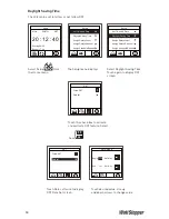
4. Touch the <Rotate> icon on the Home page of LCD screen until the Relays screen is
displayed.
5. Touch each relay to toggle the relay on and off.
6. Confirm that all of the relays switch and that the loads turn on and off.
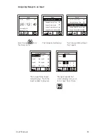
Connecting Low Voltage Switches to the LC8
The LC8 will operate with a variety of low voltage switch types including 2 wire momentary,
3 wire momentary, or maintained contact. Switches may be connected to the input terminal
blocks 1- 8 and configured to control relays or channels. Connect switches per the following
diagrams:
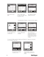
Wiring DPST Loads
1. Connect the load wires to the Output 1 and Output 2 terminal blocks on the LCDP-1 double
pole relay module.
2. Connect the double pole circuit to be controlled to the Input 1 and Input 2 terminal blocks.
3. Note that the LCDP-1 relay module contains one double pole relay. Thus, all connections
to each LCDP-1 relay module are for the same load.
Fig. 4: Relay for DPST Loads
Home
02/07/11
20 : 12 : 40
MON
Sunrise 06:39
Sunset 17:24
DST
Local - Relays
[1] Off
[2] ---
[3] Off
[4] ---
[5] Off
[6] Off
[7] Off
[8] Off