


Watlow F4T Install & Troubleshooting
•
31
•
Chapter 4 Calibration
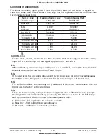
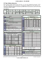
Calibration of Analog Inputs
To calibrate an analog input, you will need to provide a source of two electrical signals or
resistance values near the extremes of the range that the application is likely to utilize. See
recommended values below:
Sensor Type
Precision Source Low Precision Source High
Thermocouple
0.000 mV
50.000 mV
Millivolts
0.000 mV
50.000 mV
Volts
0.000V
10.000V
Milliamps
0.000 mA
20.000 mA
100 Ω RTD
50.00 Ω
350.0 Ω
1,000 Ω RTD
500.0 Ω
3,500 Ω
Thermistor 5 kΩ
50.00
5,000
Thermistor 10 kΩ
150.0
10,000
Thermistor 20 kΩ
1,800
20,000
Thermistor 40 kΩ
1,700
40,000
Potentiometer
0.000
1,200
CAUTION:
ç
Control loops, alarms, limits and any other functions that receive signals from the analog
input will act on the high and low signals applied in this procedure.
Note:
When calibrating a Universal Input configured as a 3-wire RTD, ensure that the calibrated
source is connected across R and both T and S inputs.
Note:
If the user exits this procedure at any point by clicking cancel or simply navigating away
to another screen, the previous calibration for the selected input will be restored.
Note:
The calibration values entered using this procedure will be overwritten whenever the con-
troller has the factory settings restored.
Note:
There are three security settings that can be applied to the calibration screens through
the
Diagnostics and Troubleshooting
(see the System Overview section of the F4T Setup
and Operation User's Guide for more information) access point:
1. Full Access - full capabilities to calibrate available
2. Read Only - first calibration screen displayed
3. No Access - calibration screens not available
Anderson-Bolds ~ 216-360-9800
www.anderson-bolds.com


