


Watlow F4T Install & Troubleshooting
•
24
•
Chapter 2 Install and Wire
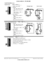
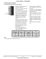
Communications Connections
EIA-232/485 Modbus RTU Communications
485 common
485 T+/R+
CB
CA
CC
CB
CA
C5
C3
C2
Slot B, E
485 T-/R-
485 T+/R+
485 T-/R-
232 common
232 (TX) to DB9 pin 2 (RD)
232 (RD) to DB9 pin 3 (TX)
• Wire T-/R- to the A terminal
of the EIA-485 port.
• Wire T+/R+ to the B terminal
of the EIA-485 port.
• Wire common to the common
terminal of the EIA-485 port.
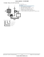
• Do not route network wires
with power wires. Connect
network wires in daisy-chain
fashion when connecting
multiple devices in a net-
work.
• A termination resistor may be
required. Place a 120 Ω resis
-
tor across T+/R+ and T-/R- of
last controller on network.
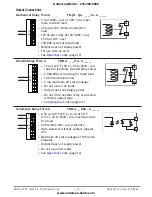
• Do not wire to both the EIA-
485 and the EIA-232 pins at
the same time.
• Two EIA-485 terminals of
T/R are provided to assist in
daisy-chain wiring.
• Do not connect more than
one controller on an EIA-232
network.
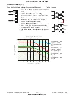
• Do not connect more than 16
controllers on a Standard Bus
EIA-485 network.
• Maximum number of control-
lers on a Modbus network is
247.
• Maximum EIA-232 network
length: 15 meters (50 feet)
• Maximum EIA-485 network
length: 1,200 meters (4,000
feet)
• 1/8th unit load on EIA-485
bus.
Modbus-IDA
Terminal
EIA/TIA-485
Name
Watlow Terminal
Label
Function
DO
A
CA or CD
T-/R-
D1
B
CB or CE
T+/R+
common
common
CC or CF
common
Note:
:
This module must be placed in slot 6.
Anderson-Bolds ~ 216-360-9800
www.anderson-bolds.com


