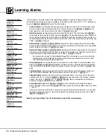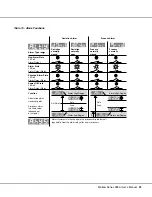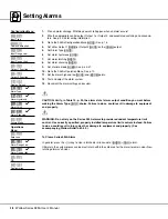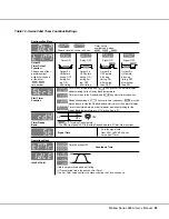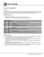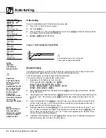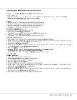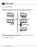
3 0
Watlow Series 935A User’s Manual
30
15
45
0
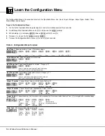
1.
Plan a timer strategy.
2.
Wire the Output 2 control output, associated switching devices and annunciators. See p. 42-45.
3.
Go to the 935A’s Configuration Menu
[CnFG]
.
4.
Choose the Output 2
[`Ot2]
function as time; hrs:min
[thM]
, or time; min:sec
[tMS]
.
5.
Choose a display default
[dISP]
• Actual Temperature only
[``Ac]
• Actual; Set Point
[AcSP]
• Actual; Time
[Acti]
• Time; Actual
[tiAc]
• Time; Set Point
[tiSP]
6.
Choose a Timer Output Function
[tIM]
:
• Delay ON
[dLon]
• Delay off
[dLoF]
• Signal ON
[sgon]
• Signal off
[sgoF]
7.
Choose a start timer
[Strt]
function; either immediate
[IMd]
, ready band
[`rdY]
, Ready
Acknowledge
[rdYA]
, or Power
[PWr]
.
8.
If you chose
[`rdY]
or
[rdya]
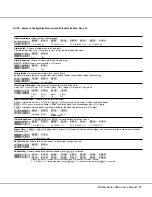
, then select a ready band
[`rdy]
value.
9.
If you chose
[SGon]
or
[sgof]
, then select a signal time
[``St]
value.
10. Go to the 935A’s Operation Menu.
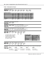
11. Set the countdown time
[tMr]
.
12. Choose the idle set point
[IdLE]
to track
[trAc]
the primary set point, or select a separate idle set
point value between the range high
[``rh]
and range low
[``rL]
values.
13. Run the system, and test the timer start with a
ß
press.
14. Document the timer settings and system.
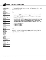
Configuration Menu
[``In]
Input Type
[`C_F]
Celsius/Fahrenheit
[``rL]
Input Range Low
[``rh]
Input Range High
[`Ot1]
Output 1 Function
[`Ot2]
✓
Output 2 Function
[dISP]
✓
Display Default
[ALty]
Alarm Type
[AhYS]
Alarm Hysteresis
•
•
•
[tIM]
✓
Timer Function
[Strt]
✓
Start Timer
[`rdY]
✓
Timer Ready Band
[``St]
✓
Signal Time
Operations
Menu
[`Aut]
Auto-tune
[tMr]
✓
Countdown Timer
[IdLE]
✓
Idle
Setting the Countdown Timer

