


Installation
•
Installing a Second Tower
Watkiss DigiVAC Service Manual - Issue 2 - 29/11/04
123
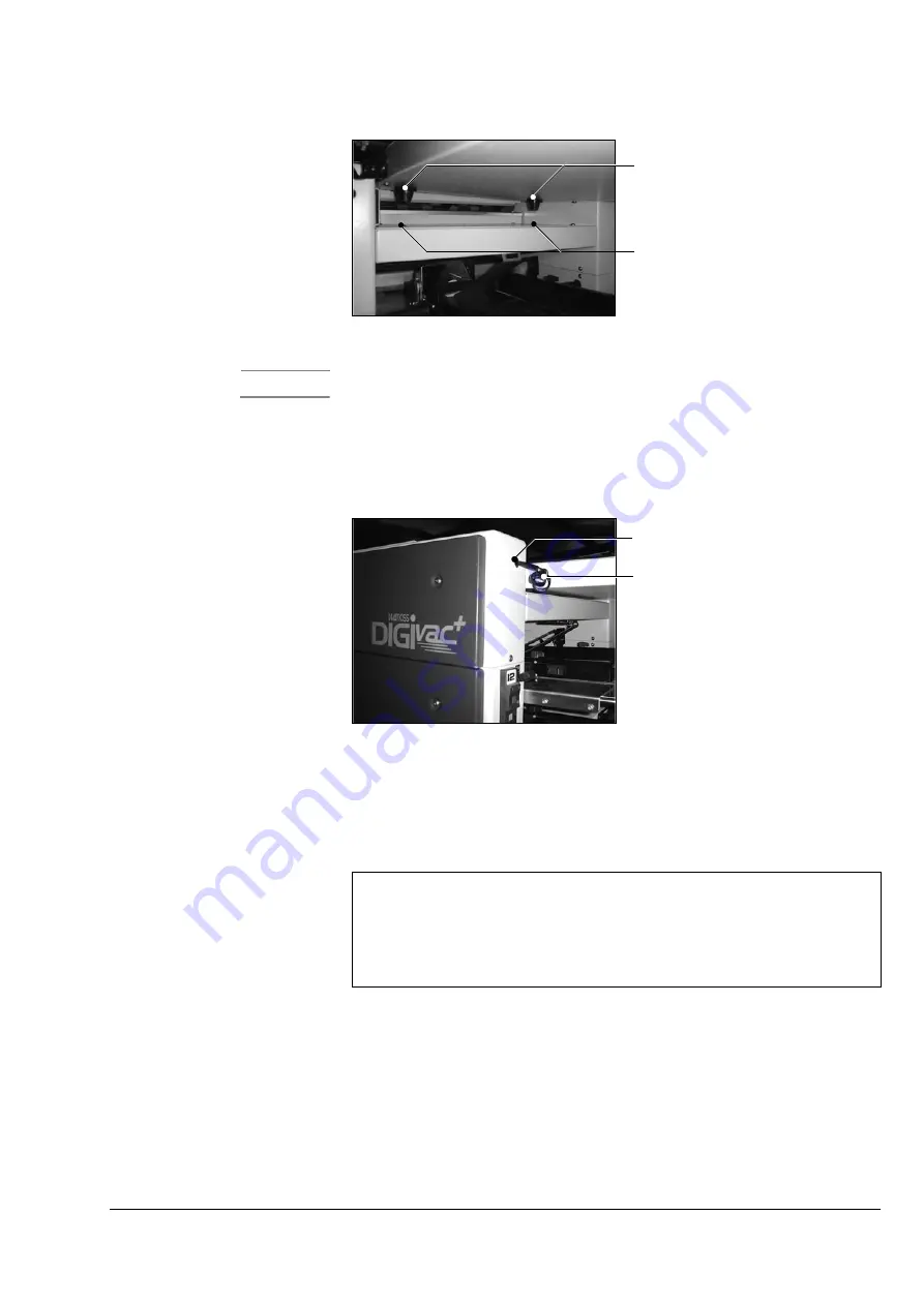
Figure 7:12 Tower Link Assembly Locating Pegs
Caution
Always move the DigiVAC to alter the alignment when guiding the tower link
assembly into the docking position. Applying lateral forces on the tower link
assembly to move the collator can result in damage.
4. Plug the tower link assembly communications cable into the socket pro-
vided on the Tower A top module.
Figure 7:13 Tower Link Assembly Communications Cable
5. Adjust the jacking screws on each of the tower bases to stabilise the
machines and prevent them from moving.
6. Switch on Tower B and then Tower A. Load the latest software (V2.1a or
later) into both towers.
7. Switch off both towers.
8. Switch on Tower A. On the GUI, select the
USER SETTINGS
menu from the
control panel. Select the
SERVICE
access level from the drop down menu
and enter the relevant access code.
9. Select the
MACHINE OPTIONS
menu and set the
MULTITOWER
function to
INLINE A
. Switch Tower A off again.
10. Switch on Tower B and allow it to fully boot-up before switching on
Tower A. The on-screen mimic should now display a two-tower Digi-
VAC.
Locating Pegs
Docking holes
Note
Two tower DigiVAC support was introduced in GUI S/W version V2.1a. This is the
minimum required.
Both towers MUST have the same version of software installed.
It is strongly recommended that the latest released version of S/W is always used if
possible.
Communications Cable
Socket


