background image


RS1  


Installation

-Softener Location / Other Requirements-

•  Locate the unit near an unswitched, 120 volt / 60 Hz grounded electrical outlet.
•  Check for distance and proper drain installation (e.g. floor drain, washing machine standpipe).
•  Determine type and size of piping required for softener connection (e.g. copper, galvanized, PVC plastic).

Note

•   If household plumbing is galvanized and you intend to make the installation with copper (or vise versa),   


    obtain di-electric unions to prevent dissimilar metal corrosion.

•  

 Where the drain line is elevated above the control valve or exceeds 20 feet in length to reach the drain,  


    use 3/4" I.D. drain line tubing instead of 1/2" I.D. Drain line tubing is not included.

•  

All plumbing lines not requiring “soft” water should be connected “upstream” of the softener. 

•  

The cabinet brine tank drain line is gravity flow and must discharge below the overflow fitting.

•  

The cabinet brine overflow is provided as a back-up in the event the safety float shut-off should fail, allowing the  

    brine tank to overfill. This drain connection would then carry the excess water to the drain and prevent flooding of  
    the floor. Therefore, no liability will or can be assumed by the manufacturer of the softener should this occur.

Caution 

•  

If sweat soldering copper pipe (remember to always use lead free solder and flux), cover bypass valve with wet rags  

   to prevent heat damage to connections and control valve! If using PVC or plastic pipe
   primers and solvent cements specifically recommended for use with potable water are required.

-Installation Procedure-

- Water Supply Connections and Bypass Valve -

To allow for softener servicing, swimming pool filling or lawn sprinkling, a manual bypass valve has been installed

at the factory. The bypass allows hard water to be manually routed around the softener.

1.  Position softener at desired location for installation. (See Installation Diagrams.)

2.Turn OFF main water supply and OPEN nearest faucet to relieve pressure.

3.  Cut main line and install appropriate elbows and extensions. Inlet and outlet connections on the control valve are  
     3/4” FNPT. 

Caution : 

Raised arrows located on the sides of control valve body and bypass valve indicate proper direction of water  


    flow. Install inlet and outlet piping in direction of arrows.

4. Rotate bypass valve to the bypass position (position of lever is at right angle to inlet / outlet piping).

5. Turn the main supply line on to restore water service to the home.

6. OPEN nearest faucet to evacuate air and repressurize plumbing lines.

7. Check for leaks!


6

Summary of Contents for rs1

Page 1: ...RS1 RS1 Softener Manual Installation Operation Manual CABINET Water Softener...

Page 2: ...ation Page 5 Master Programming Page 12 Utilizing Bluetooth Page 14 Powerhead Assembly Page 15 Valve Body Assembly Page 16 Cabinet Body Assembly Page 17 Bypass Assembly Page 18 Additional Information...

Page 3: ...that attacks some plastic materials It is recommended that Teflon tape be used to seal plastic Noryl threaded fittings Softener Specifications 3 General Specifications CD24 CD24X CD32 CD32X Grains Cap...

Page 4: ...oft water The surfaces of these beads are covered with sodium ions As hard water enters the mineral tank and comes into contact with the resin an ex change of ions takes place as dissolved Calcium and...

Page 5: ...lumbing connections A level floor position ahead of piping into water heater Unit must be installed at least 10 ahead of the inlet to a water heater to prevent damage due to back up of hot water DO NO...

Page 6: ...assumed by the manufacturer of the softener should this occur Caution If sweat soldering copper pipe remember to always use lead free solder and flux cover bypass valve with wet rags to prevent heat...

Page 7: ...low during regeneration Elbows or other fittings must be kept at a bare minimum Note Where the drain line is elevated above the control valve or exceeds 20 in length 3 4 I D drain line tubing should b...

Page 8: ...ss the Menu Enter button Time of Day will flash 2 To set the Time of Day press the Set Change button First digit will flash Example 12 00 To change digit value press the Set Change button To accept th...

Page 9: ...run to drain for 3 to 4 minutes Warning Close valve on bypass prior to selecting the backwash position After backwash position has been established slightly open bypass to evacuate air from the media...

Page 10: ...d Final Check 1 Be certain the bypass valve is in the SERVICE position 2 Make sure the power supply is connected to an uninterrupted 115 volt outlet 3 Check that the time of day is set 4 Double check...

Page 11: ...Time of Day and Gallons left until the next regeneration The meter will count down to zero 0000 and then regenerate at the scheduled time set Starting Extra Regeneration Cycle 1 To Start Delayed Extr...

Page 12: ...is used to set the maximum amount of time in days the unit can be in service without regeneration This setting is identified by the letter A in the left digit Regeneration will begin at the scheduled...

Page 13: ...1 ON BE 0 OFF 7 Bluetooth Password BBPP is displayed for one second then password is displayed 8 To Exit the Master Programming Mode press the Menu Enter button until time of day returns Note If no bu...

Page 14: ...this device must accept any interference received including interference that may cause undesired operation Changes or modifications not expressly approved by the party responsible for compliance coul...

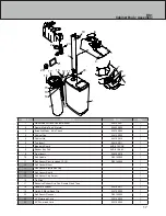
Page 15: ...Number Qty 1 Secondary Plate 20016X002 1 2 Encoder Wheel 20001X007 1 3 Encoder Board 20016X200 1 4 Main Plate 20016X001 1 5 Motor 20016X200 1 6 Brine Cam 20001X122 1 7 Main Gear 20001X120 1 6 1 2 7 4...

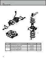
Page 16: ...Ferrule 20251X305 2 12 Injector Cap Screw 20001X226 1 13 Injector Cap 20001X223 1 Ref Description Part Qty 14 Injector Seal 20001X224 1 15 Injector White 20001X219 1 16 Screen 20001X222 1 17 Plug 2000...

Page 17: ...6X011 1 7 Bluetooth Board EVB 019 CAB 1 8 Rubber Key Pad EVA 019 KEY 1 9 Front Insert 20016X012 1 10 Salt Paddle R2014X002 1 11 Salt Sensor Pivot includes 12 15 R2014X005 1 12 Salt Sensor Mount 1 13 S...

Page 18: ...y Ref Description Part Qty 1A Meter Assembly Turbine Complete 20003X200 1 1 Plastic Bypass Valve Assembly 20561X292 1 2 Bypass Valve 3 4 Stainless Steel 20561X270 1 Bypass Valve 1 Stainless Steel 2056...

Page 19: ...s and remove cap 3 Remove injector assembly Apply silicone lubricant to new injector assembly O rings and install Be sure to push injector assembly tightly so O rings are seated Install a new screen 4...

Page 20: ...to assure proper function Make sure control valve is returned to the service position 13 Make sure there is enough salt in the brine tank 14 Start regeneration cycle manually if water is hard 15 Repla...

Page 21: ...body Install new seals and spacers individually pressing around the outer edge of each seal to make sure it is seated When all seals and spacers are seated properly you will have a 1 4 of space betwe...

Page 22: ...ver it Resin fouling Call dealer Find out how to confirm it Clean the resin and prevent future fouling Poor distribution channeling uneven bed surface Call dealer Check backwash flow Regenerate more f...

Page 23: ...tionsfor air leaks Internal control leak Call dealer Check piston seals and spacers for scratches and dents 9 Continuous Flow to Drain Foreign material in control piston and seals Call dealer Clean va...

Page 24: ...RS1 WATERSOFT 710 Orange St Ashland OH 44805 l PH 419 281 6829 l FAX 419 281 2375 www WATERSOFT com...

Reviews: