TA I
NSTRUMENTS
S
AMPLE
/T
EMPERATURE
TAGE
i
Thermal Analysis & Rheology
A S
UBSIDIARY
OF
W
ATERS
C
ORPORATION
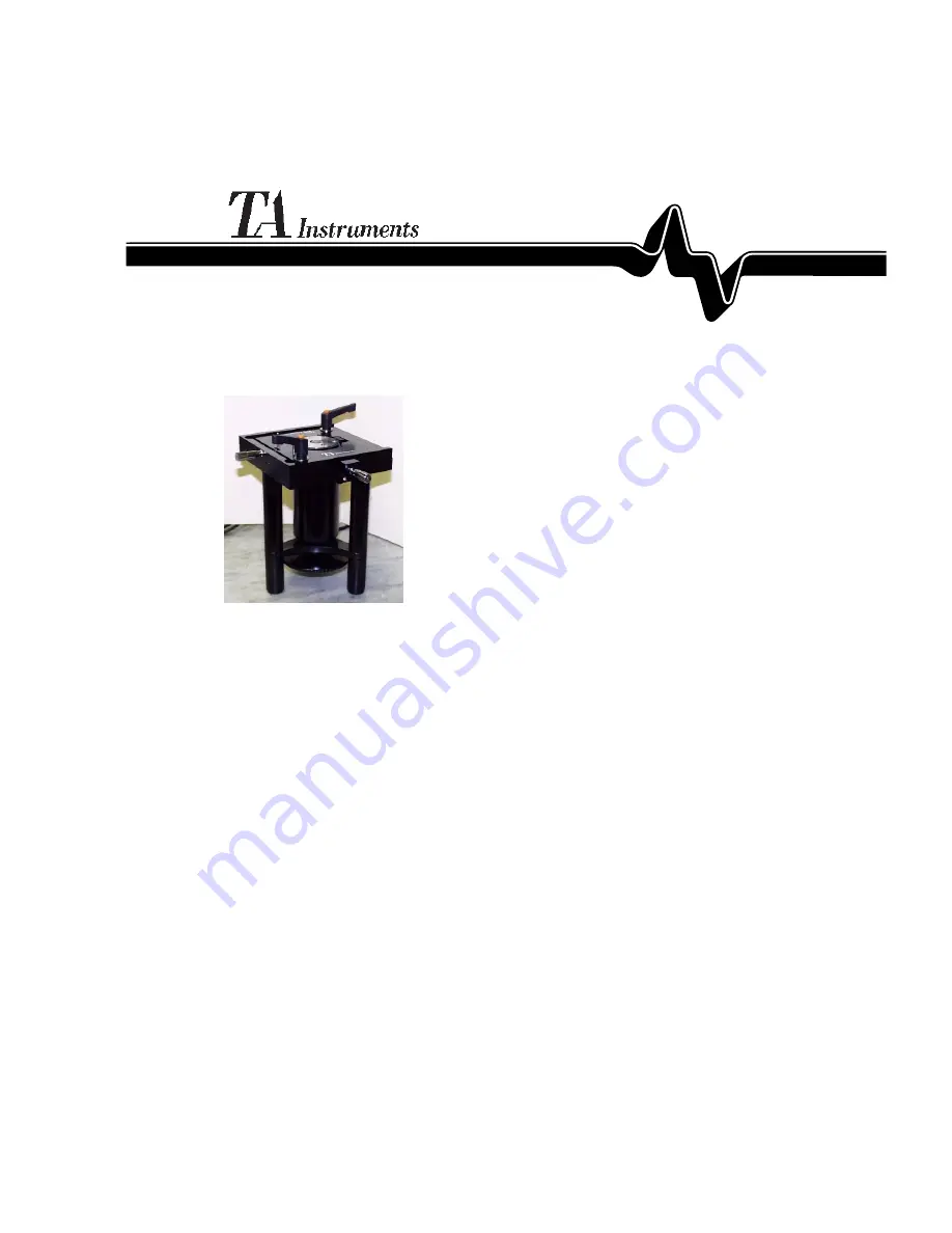
Sample/ Temperature Stage
Accessory for the µTA 2990
TM
Operator's Guide
PN 899038.001
Rev. A
Issued July 2000
Page 1: ...STRUMENTSSAMPLE TEMPERATURE STAGE i Thermal Analysis Rheology A SUBSIDIARY OF WATERS CORPORATION Sample Temperature Stage Accessory for the TA 2990 TM Operator s Guide PN 899038 001 Rev A Issued July...
Page 2: ...onorliability Thispublication is not a license to operate under or a recommen dation to infringe upon any process patents TA Instruments Instrument Control Data Analysis and Utility Software and their...
Page 3: ...genAbsorption xi Instrument Symbols xiii Introducing the Sample Temperature Stage 1 1 Description 1 2 Specifications 1 4 Principles of Operation 1 5 Installing theSample Temperature Stage 1 7 Choosing...
Page 4: ...ture 1 20 Using the Start Finish Button 1 21 Using the Hold Button 1 22 Using the Heat Cool Button 1 23 Sample Procedure 1 24 PerformingTemperature Calibration 1 25 Removing the Old Calibration Factor...
Page 5: ...ne the Thermal Analysis Help Desk at 302 427 4070 SERVICE U S A For instrument service and repairs phone 302 427 4050 TA Instruments Ltd Europe House Bilton Centre Cleeve Road Leatherhead Surrey KT22...
Page 6: ...he Netherlands A Division of Waters Chromatography B V Florijnstraat19 4879 AH Etten Leur Telephone 31 76 508 72 70 Fax 31 76 508 72 80 TA Instruments Japan No 5 Koike Bldg 1 3 12 Kitashinagawa Shinag...
Page 7: ...perature Stage refer to the follow ing list of parts and then contact your service representative or the TA Instruments office closest to you A list of the offices can be found on page v Part Number D...
Page 8: ...importance and safety as you read through the instructions A NOTE highlights important information about equipment or procedures A CAUTION emphasizes a procedure that may damage equipment or cause los...
Page 9: ...taken to avoid direct contact while the instrument hardware is powered on Call TA Instruments Service for repairs We do not recommend that you make any attempt to remove the panels on the instrument I...
Page 10: ...e air in the room you are in 3 Generate very high pressures if trapped in lines or containers Handling Liquid Nitrogen 1 Wear goggles or a face shield gloves large enough to be removed easily and a ru...
Page 11: ...quid nitrogen came in contact with your eyes Room Ventilation Liquid nitrogen evaporates quickly at room temperature and could replace the air in a room Use liquid nitrogen in a well ventilated room O...
Page 12: ...liquid nitrogen container in a confined space Do not enter a confined space where nitrogen gas may be present unless the area is well ventilated The above warning applied to the use of liquid nitrogen...
Page 13: ...xplanation Indicates the presence of high voltage Turn off the power to the instrument when directed Follow all safety precautions listed in this manual to avoid injury Please heed these labels and ta...
Page 14: ...xiv TA INSTRUMENTS SAMPLE TEMPERATURESTAGE Sample Temperature Stage...
Page 15: ...on the Sample Temperature Stage and you can begin scanning as described in the TA 2990 Operator s Manual You will find that using the Sample Temperature Stage has the following advantages when perform...
Page 16: ...ists of the following A platform with a magnetic plate on three legs Two knurled knobs on the sides allow the sample platform to be moved in the X and Y directions A large knurled wheel at the bottom...
Page 17: ...oller which is used to control heating and cooling of the sample during scans at other than ambient temperatures Do not heat the Temperature Stage above 250 C Doing so would depolarize the sample moun...
Page 18: ...rmation about the Sample Temperature Stage product specifications Table 1 Sample Temperature Stage Specifications Dimensions Stage Height 24 cm 9 5 in Width 18 cm 7 in Depth 22 cm 8 5 in Controller He...
Page 19: ...The temperature sensor is located near the sample mount for temperature accuracy The Stage Controller has been specifically designed for precise temperature control of the Temperature Stage The Stage...
Page 20: ...inger controls the rate and limit of cooling of the sample The Sample Stage provides the X Y and Z sample movements without temperature adjust mentcapability The Temperature Stage can be used with bot...
Page 21: ...afterinstallation Seepage25for instructionontemperaturecalibration Choosing a Location The Sample Temperature stage is designed to operate safely in the same environment as the TA 2990 with which it i...
Page 22: ...etimes lost in the packing material Please check through the material carefully before discarding the container Follow these instructions to unpack the compo nents of the Sample Temperature Stage As y...
Page 23: ...igure 2 b Plug the power cord of the controller to a main outlet 5 Connect the cable from the Stage to the back of the controller as shown in Figure 2 High voltage is present at the PC board and conne...
Page 24: ...Sample Temperature Stage 10 TA INSTRUMENTS SAMPLE TEMPERATURE STAGE Figure 2 Rear Panel of Stage Controller Installation...
Page 25: ...perature Stage before you scan using the cooling function Otherwise the sample area would frost up during cooling interfering with scanning results Use the following procedure to install the sample co...
Page 26: ...e position previously occupied by the dress shield Ensure that The long thin slot in the plastic shield somewhat parallels the X scanning angle of the Z scanner with the curb being close to the scanne...
Page 27: ...ogen is used are well ventilated to prevent displacement of oxygen in the air 1 Press the Start Finish button on the Stage Controller 2 Turn the Limit knob on the controller counterclockwise until the...
Page 28: ...Sample Temperature Stage 14 TA INSTRUMENTS SAMPLE TEMPERATURESTAGE 7 Remove the funnel and replace the TA head Figure 4 Filling the Canister with Liquid Nitrogen...
Page 29: ...the sample platform under the probe to limit the use of the motor for alignment To heat or cool the sample to a desired temperature for imaging and TA Basic Procedure The basic procedure for using the...
Page 30: ...on the probe Also fill the canister with liquid nitrogen if needed see page 13 DO NOT use the sample cover when scanning at temperatures above 70 C The plastic in this part will melt at higher temper...
Page 31: ...troller Front Panel When the Stage Controller is powered on the display screen shows TA Instruments and the Power LED green lights up The display then changes to show three readings left to right rate...
Page 32: ...ough 90 C minute in increments of 10 Use the Rate Step button to change the heating or cooling rate A single press of this button raises the displayed value by one unit either 0 1 1 0 or 10 depending...
Page 33: ...ayed is 10 but you wish to use a value between 0 1 and 0 9 press the Rate 10 button twice the value changes to 0 1 Then use the Rate Step button the select the value you want in that range If the valu...
Page 34: ...s the displayed value The values available on the Stage Controller for target temperature range from 200 to 600 C in whole numbers However the lower and upper limits for the actual Temperature Stage a...
Page 35: ...pressed When you have mounted a sample and entered the parameters for heating cooling or isothermal scanning press the Start Finish button The Load LED begins to flash to indicate that the Stage Cont...
Page 36: ...mple Temperature Stage is actually heating or cooling When the Hold button is pressed the screen alternately displays the word Hold and the current temperature You can also use Hold mode to change the...
Page 37: ...rature pressing the Heat Cool button starts it cooling The word Cool is displayed where the target temperature value was Once the temperature reaches the target temperature for the Temperature Stage t...
Page 38: ...the Ratex10 button once The display now reads 20 4 Press the Rate Step button 8 times until the rate value is 10 5 Press the Start Finish button on the Stage Controller 6 Turn theLimit knob countercl...
Page 39: ...on Factors Before a new set of calibration values can be determined on the Temperature Stage the existing calibration factors must be removed This step ensures that the Stage Controller will read the...
Page 40: ...nd enter Values 1 and 2 when prompted For this procedure you will need the following items which can be found in your TATM 2990 accessory kit A few milligrams of a temperature reference material i e a...
Page 41: ...Press the Start Finish button to halt the program and remove the sample You can now enter the new calibration factors Entering the New Calibration Factors 1 Turn the power for the Stage Controller off...
Page 42: ...2 6 Turn the Limit knob again until the mea sured positive value that is the tempera ture you recorded from the display when the sample material had completely melted For example Value 2 70 C The Sta...
Page 43: ...ssembly 1 8 B basic procedure 1 15 C canister 1 2 filling with liquid nitrogen 1 13 coolant 1 5 cooling 1 5 cooling canister See canister D description 1 1 E electrical WARNING 1 9 H Heat Cool button...
Page 44: ...e Stage Control ler 1 18 Rate Step button 1 18 Rate 10 button 1 19 Ratex10 button 1 19 reference material 1 26 S Safety liquid nitrogen x safety ix to x L LicensingAgreement ii Limit knob 1 17 liquid...
Page 45: ...esistance 1 25 specifications 1 4 Stage Controller 1 2 1 5 setting the rate 1 18 using 1 17 Stage sensor 1 5 Start Finish button 1 21 subambient operation 1 5 T TA Instruments addresses and phone numb...
Page 46: ...32 TA INSTRUMENTS SAMPLE TEMPERATURESTAGE Sample Temperature Stage...