June 28, 2016, 715003956 Rev. C
Page 92
4.
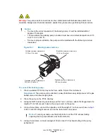
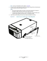
Connect the 90-degree elbow to the free end of the PTFE tubing that runs alongside the
instrument.
5.
Connect the second length of PTFE tubing to the other end of the 90-degree elbow.
6.
Connect the free end of the second length of PTFE tubing to the inlet of the exhaust-trap
bottle.
7.
Using the third length of PTFE tubing, connect the exhaust-trap bottle’s outlet to the
laboratory exhaust system (see the figure on
, for a complete exhaust
configuration).
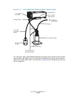
Figure D–9:
Rear configuration without LC stack or bottom of stack
Tip:
This figure shows a QDa Detector fitted with the external, source exhaust valve assembly
(serial number suffix "KAB"). To see the QDa Detector fitted with the internal, source exhaust
valve (serial number suffix "KAD"), see the figures on
(rear configuration) and
(front configuration).
Notice:
To prevent solvent leaks and resultant damage to the instrument, ensure that
the entire PTFE waste line, from the instrument to the exhaust-trap bottle, follows a
continuous, downward gradient, without loops or areas of compression.
Source
exhaust
valve
assembly
90-degree elbow
To laboratory
exhaust system
Exhaust-trap bottle
ACQUITY QDa
PTFE tubing
PTFE tubing (ensure
downward gradient)
Convoluted liquid
waste tubing
Liquid waste
container
Exhaust solenoid cable


