IM2700AN 06/13
Installation Information
Water Piping Connections
Hot Water Generator Connections
Electrical
Startup Procedures
Troubleshooting
Preventive Maintenance
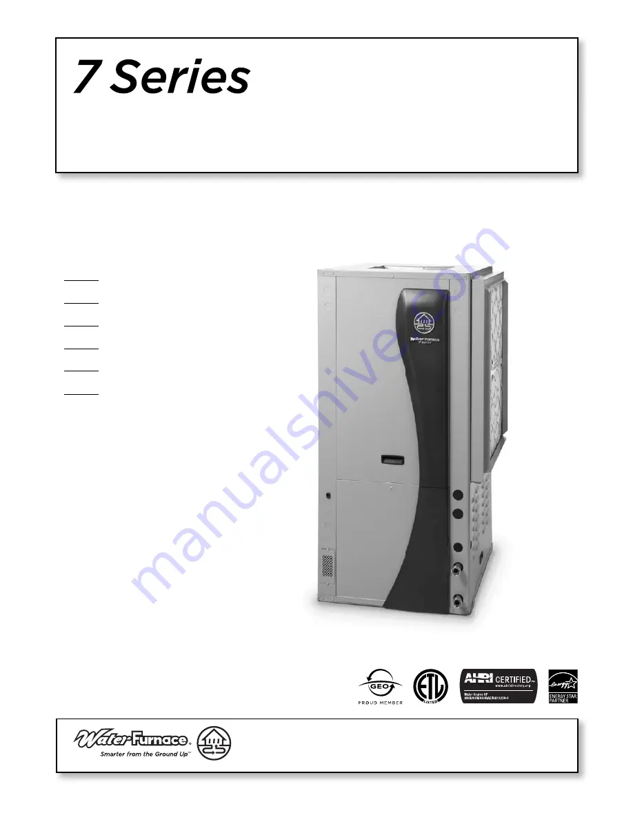
7 Series 7
00A11 Ins
tallation Manual
Geothermal Heat Pump
•
R-410A
Refrigerant
• 3, 4, 5 Ton Variable Speed
700A11
C
US


