nominal flow. Heaters, automatic filters and the viscosimeter should be bypassed to prevent
damage caused by debris in the piping. The automatic fuel filter must not be used as flushing
filter.
The pump used should be protected by a suction strainer. During this time the welds in the
fuel piping should be gently knocked at with a hammer to release slag and the filter inspected
and carefully cleaned at regular intervals.
The cleanliness should be minimum ISO 4406 (c) 20/18/15, NAS9. A measurement certificate
shows required cleanliness has been reached there is still risk that impurities may occur after
a time of operation.
Note! The engine must not be connected during flushing.
5.7.3
Lubricating oil pipes
Flushing of the piping and equipment built on the engine is not required and flushing oil shall
not be pumped through the engine oil system (which is flushed and clean from the factory).
It is however acceptable to circulate the flushing oil via the engine sump if this is advantageous.
Cleanliness of the oil sump shall be verified after completed flushing and is acceptable when
the cleanliness has reached a level in accordance with ISO 4406 (c) 21/19/15, NAS10. All
pipes connected to the engine, the engine wet sump or to the external engine wise oil tank
shall be flushed. Oil used for filling shall have a cleanliness of ISO 4406 (c) 21/19/15, NAS10.
Note! The engine must not be connected during flushing
5.7.4
Pickling
Prefabricated pipe spools are pickled before installation onboard.
Pipes are pickled in an acid solution of 10% hydrochloric acid and 10% formaline inhibitor for
4-5 hours, rinsed with hot water and blown dry with compressed air.
After acid treatment the pipes are treated with a neutralizing solution of 10% caustic soda
and 50 grams of trisodiumphosphate per litre of water for 20 minutes at 40...50°C, rinsed with
hot water and blown dry with compressed air.
Great cleanliness shall be approved in all work phases after completed pickling.
5.8
Flexible pipe connections
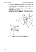
All external pipes must be precisely aligned to the fitting or the flange of the engine to minimize
causing external forces to the engine connection.
Adding adapter pieces to the connection between the flexible pipe and engine, which are not
approved by Wärtsilä are forbidden. Observe that the pipe clamp for the pipe outside the
flexible connection must be very rigid and welded to the steel structure of the foundation to
prevent vibrations and external forces to the connection, which could damage the flexible
connections and transmit noise. The support must be close to the flexible connection. Most
problems with bursting of the flexible connection originate from poor clamping.
Proper installation of pipe connections between engines and ship’s piping to be ensured.
●
Flexible pipe connections must not be twisted
●
Installation length of flexible pipe connections must be correct
●
Minimum bending radius must be respected
●
Piping must be concentrically aligned
●
When specified, the flow direction must be observed
●
Mating flanges shall be clean from rust, burrs and anticorrosion coatings
DAAB605814
5-5
5. Piping Design, Treatment and Installation
Wärtsilä 46F Product Guide
Summary of Contents for 46F Series
Page 1: ...Wärtsilä 46F PRODUCT GUIDE ...
Page 4: ...This page intentionally left blank ...
Page 8: ...This page intentionally left blank ...
Page 18: ...This page intentionally left blank ...
Page 86: ...This page intentionally left blank ...
Page 104: ...This page intentionally left blank ...
Page 154: ...This page intentionally left blank ...
Page 162: ...This page intentionally left blank ...
Page 170: ...This page intentionally left blank ...
Page 176: ...This page intentionally left blank ...
Page 194: ...This page intentionally left blank ...
Page 200: ...This page intentionally left blank ...
Page 202: ...This page intentionally left blank ...
Page 207: ...Fig 21 7 List of symbols DAAF406507 7 DAAB605814 21 5 21 ANNEX Wärtsilä 46F Product Guide ...

