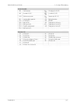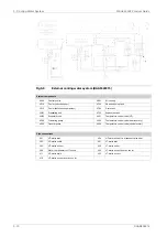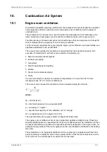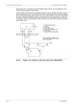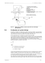
Fig 10-2
Engine room ventilation, air duct connected to the turbocharger
(DAAE092652A)
10.2
Combustion air system design
Usually, the combustion air is taken from the engine room through a filter on the turbocharger.
This reduces the risk for too low temperatures and contamination of the combustion air. It is
important that the combustion air is free from sea water, dust, fumes, etc.
For the required amount of combustion air, see section Technical data.
The combustion air shall be supplied by separate combustion air fans, with a capacity slightly
higher than the maximum air consumption. The combustion air mass flow stated in technical
data is defined for an ambient air temperature of 25°C. Calculate with an air density
corresponding to 30°C or more when translating the mass flow into volume flow. The expression
below can be used to calculate the volume flow.
where:
combustion air volume flow [m³/s]
q
c
=
combustion air mass flow [kg/s]
m' =
air density 1.15 kg/m³
ρ
=
The fans should preferably have two-speed electric motors (or variable speed) for enhanced
flexibility. In addition to manual control, the fan speed can be controlled by engine load.
In multi-engine installations each main engine should preferably have its own combustion air
fan. Thus the air flow can be adapted to the number of engines in operation.
The combustion air should be delivered through a dedicated duct close to the turbocharger,
directed towards the turbocharger air intake. The outlet of the duct should be equipped with
DAAB605814
10-3
10. Combustion Air System
Wärtsilä 46F Product Guide
Summary of Contents for 46F Series
Page 1: ...Wärtsilä 46F PRODUCT GUIDE ...
Page 4: ...This page intentionally left blank ...
Page 8: ...This page intentionally left blank ...
Page 18: ...This page intentionally left blank ...
Page 86: ...This page intentionally left blank ...
Page 104: ...This page intentionally left blank ...
Page 154: ...This page intentionally left blank ...
Page 162: ...This page intentionally left blank ...
Page 170: ...This page intentionally left blank ...
Page 176: ...This page intentionally left blank ...
Page 194: ...This page intentionally left blank ...
Page 200: ...This page intentionally left blank ...
Page 202: ...This page intentionally left blank ...
Page 207: ...Fig 21 7 List of symbols DAAF406507 7 DAAB605814 21 5 21 ANNEX Wärtsilä 46F Product Guide ...

