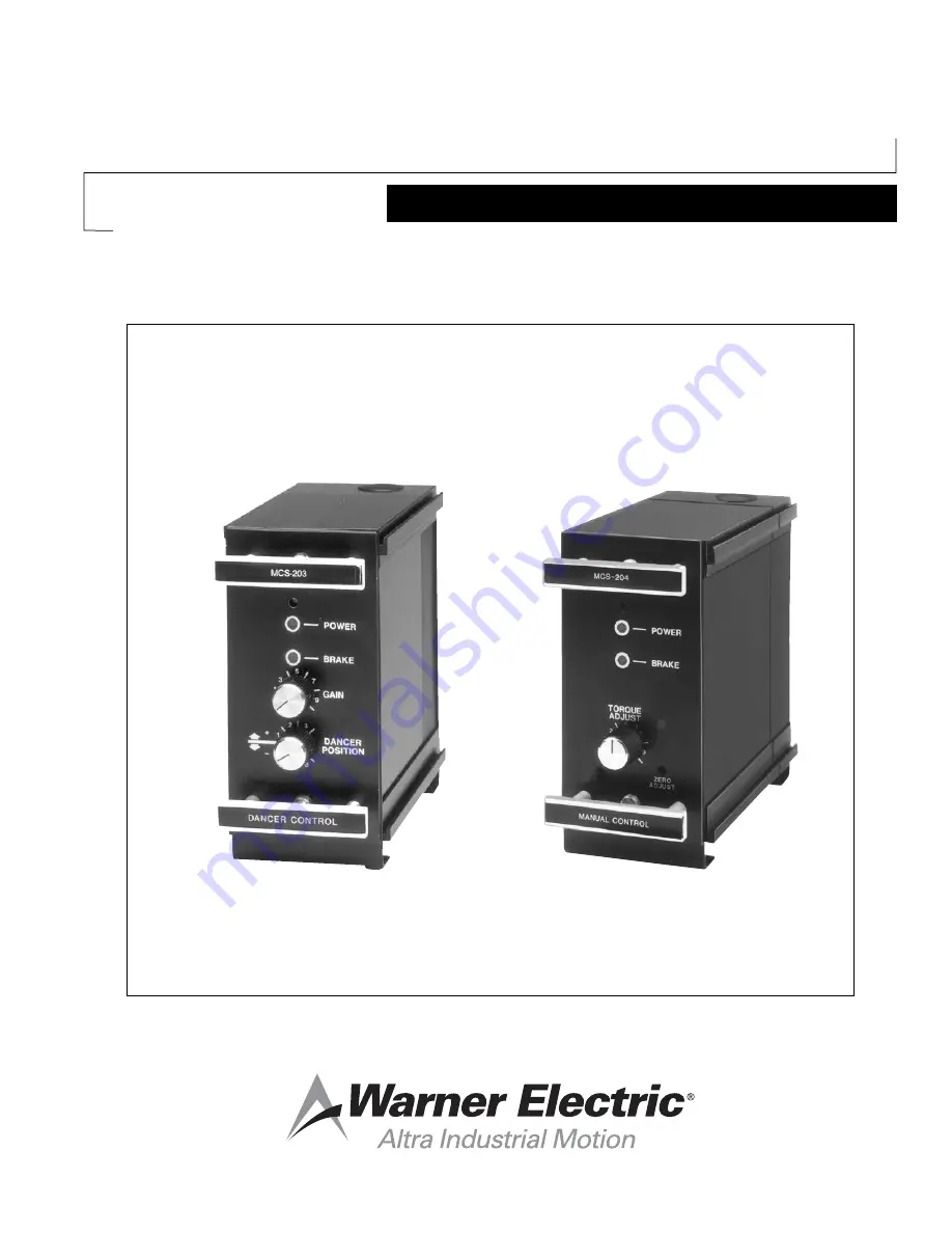
Tension Control System
MCS-166, MCS-203, MCS-204
Installation & Operation Instructions
P-0257-WE819-9027
Page 1: ...Tension Control System MCS 166 MCS 203 MCS 204 Installation Operation Instructions P 0257 WE 819 9027 ...
Page 2: ...stem Troubleshooting MCS 166 MCS 203 21 22 MCS 166 MCS 204 23 Replacement Parts Listing 24 Listing of Figures and Illustrations 24 Notes Installation must be made in accordance with the instructions found in this manual Failure to do so may damage the controls and void their warranty Warning Contact with the electrical voltages present in the controls covered in this manual can cause injury or dea...
Page 3: ...emotely by external potentiometer voltage input or current loop input The MCS 605 1 or TCS 605 5 Pivot Point Sensors provide the dancer position signal to the MCS 203 Dancer Control The MCS 605 1 is coupled to the dancer pivot when rotation is no more than 60 degrees while the TCS 605 5 covers rotation up to 300 degrees Specifications MCS 166 Power Supply Module Part Number 6910 448 013 Input Powe...
Page 4: ...o correspond to minimum output level Torque Adjust Span Provides for either manual adjust or span adjustment when in all other modes of operation General Information Control chassis must be considered NEMA1 and should be kept clear of all areas where foreign material dust grease or oil might affect the operation of the control Control chassis should be electrically grounded Neither sensor nor brak...
Page 5: ...10 bolts c Apply the terminal strip label supplied with the control logic module to the PC Board as shown in Figure 2 page 6 CAUTION Be sure to apply the label in the proper position with the brake terminal at the top d Mount the rear sections loosely to the mounting surface Do not connect the front sections yet The controls are now ready to be wired Proceed to the wiring section of this manual fo...
Page 6: ...ur 4 13 64 mounting holes for each housing to provide clearance for the 10 mounting studs 4 Slide the housing assemblies into the mounting panel cutouts Securely fasten the housings to the mounting panel with the four nuts on each housing 5 Apply the terminal strip label to the housing panel near the terminal block as shown in Figure 5 page 7 CAUTION Be sure to apply the label in the proper positi...
Page 7: ...r shaft and pin are aligned and separated by 5 16 6 While holding the sensor and bracket in this position mark the centers of the bracket holes on the machine 7 Drill and tap three 3 holes for 8 32 screws in the machine 8 Connect the sensor shaft to the pin with the supplied universal coupling The index mark on the sensor shaft must be aligned with the index mark on the sensor face when the dancer...
Page 8: ...otation as viewed from the connector end of the pivot point sensor CW a For CW rotation connect sensor wires as follows Black to Terminal 5 green to Terminal 6 red to Terminal 7 Shield lead should be connected to Terminal 7 CCW b For CCW rotation connect sensor wires as follows Red to Terminal 5 green to Terminal 6 black to Terminal 7 Shield lead should be connected to Terminal 7 5 External Switch...
Page 9: ...Warner Electric 800 825 9050 P 0257 WE 819 9027 9 Figure 7 MCS 166 MCS 203 Wiring Single Brake Figure 8 MCS 166 MCS 203 Wiring Dual Brakes ...
Page 10: ...r moving the roll follower pot toward the core will decrease voltage at terminal 6 c Voltage Source Input Connect side of external voltage source to terminal 6 and side or common of external voltage source to MCS 204 terminal 7 per Figure 11D page 12 CAUTION The input level from an external voltage source must not exceed 14 5 VDC Voltage levels higher than 14 5 VDC will damage the control s input ...
Page 11: ...ront housings if either wall or shelf mounting is used Secure the latches If shelf mounting is used secure the housings with the four 4 bolts for each section 8 Do not insert the control modules at this time Proceed to the MCS 166 MCS 204 start up section of this manual Figure 9 MCS 166 MCS 204 Wiring Single Brake Figure 10 MCS 166 MCS 204 Wiring Dual Brakes ...
Page 12: ...12 Warner Electric 800 825 9050 P 0257 WE 819 9027 Figure 11 MCS 204 Input Configuration Figure 12 Analog Photoelectric Roll Follower Wiring ...
Page 13: ...side to side until the connectors mate but do not apply excessive force NEW STYLE UNITS WITH RIBBON CABLES Pull the ribbon cable forward so that the connector end is in front of the housing assembly Fasten the ribbon cable connector to the pin connector on the control module Pin 1 Red Tracer on the ribbon cable must connect to pin 1 on the control module as shown This Red Tracer will ALWAYS be tow...
Page 14: ...erify that power is on 2 Start the machine and draw material 3 After the Dancer has stabilized adjust the front panel Dancer Position potentiometer for the desired dancer running position 4 If the system is providing stable dancer operation increase the Gain until the dancer hunts or oscillates Note the gain position number where this occurs 5 Reduce the gain setting from step 4 above one to two d...
Page 15: ...er response is not achieved with R16 at maximum CW setting the next higher differentiator response range should be used CAUTION When switching to higher response ranges R16 should be set full CCW Factory Settings P R32 100 CW I R24 60 70 CW D R 16 75 CW Dip switch 1 on only e Repeat steps b through d above to insure optimum response NOTE To insure optimum performance the system should be checked a...
Page 16: ...16 Warner Electric 800 825 9050 P 0257 WE 819 9027 Figure 13 Control Adjustment Locations MCS 166 MCS 203 ...
Page 17: ...e to side until the connectors mate but do not apply excessive force NEW STYLE UNITS WITH RIBBON CABLES Pull the ribbon cable forward so that the connector end is in front of the housing assembly Fasten the ribbon cable connector to the pin connector on the control module Pin 1 Red Tracer on the ribbon cable must connect to pin 1 on the control module as shown This Red Tracer will ALWAYS be toward...
Page 18: ...meter through front panel so the 0 100 indicator illuminates This is a true zero output to the brake c Now rotate the torque span potentiometer toward its maximum setting As the pot is turned the 0 100 indicator goes out and the brake indicator comes on At 100 output 24VDC the 0 100 indicator will come on NOTE Depending on the accuracy of the initial zero setting steps a through c above may have t...
Page 19: ...ch corresponds to the exact center of the roll shaft Adjust the roll follower potentiometer to provide a DC input reading of 0 5 VDC 0 1 VDC d Remove the meter from the follower potentiometer and connect across the brake magnet e Set the roll follower arm to correspond to the maximum roll diameter f Adjust the torque span potentiometer to provide the desired output level to the brake as indicated ...
Page 20: ...20 Warner Electric 800 825 9050 P 0257 WE 819 9027 Figure 14 Control Adjustment Locations MCS 166 MCS 204 ...
Page 21: ...eck to be sure lead wires to the brake are at the brake terminals 1 and 2 of the control Check to see if sensor is connected Using a voltmeter check for approximately 1 8 to 28 VDC between the brake terminals If there is no voltage check for approximately 1 8 to 28 VDC between terminals and 2 of the control If the voltage is present at the control and not at the brake wires to the brake are open I...
Page 22: ... does not exceed the minimum allowable torques if the voltage did reduce to zero but did not reverse polarity adjustment of the antiresidual may be necessary If adjustment of the antiresidual does not cause the brake voltage to reverse polarity in the off state replace the PC Board Assembly Symptom D Dancer moves erratically appears to hunt or oscillate Probable Cause Suggested Solution Incorrect ...
Page 23: ...e does not have the torque capacity required for the application Verify that the correct brake was selected by repeating the selection procedure Brake is not releasing as input level decreases Check the mechanical parts of the brake to assure they are in good operating condition and properly installed Check to see if Brake On input is activated Roll shaft not free to rotate with control off Inputs...
Page 24: ...023 Rear P C Board Assy MCS 204 W S end 6910 101 021 Fuse 3 Amp 250 Volt Fast Acting 458 8001 006 MCS 605 1 Pivot Point Sensor Single Turn 7330 448 002 TCS 605 5 Pivot Point Sensor 5 Turn 7330 448 003 Replacement Cable Assy for MCS 605 1 TCS 605 5 7330 101 001 Coupling 284 8000 003 New style back board assembly w ribbon cable connector assembly Listing Of Figures And Illustrations Figure 1 Wall sh...