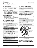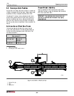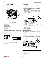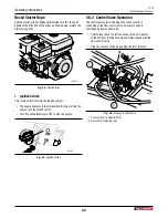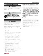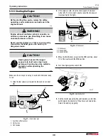
To Lower the Conveyor Angle
•
Turn the winch handle counterclockwise. No clicking sound
is heard because the brake system is activated.
00448
Fig. 12 –
Lowering Conveyor
5.4 Setting Conveyor Speed
The conveyor is powered by an external hydraulic source,
unless equipped with the accessory hydraulic power pack. The
pressure and return lines are connected to the flow control valve
on the conveyor frame.
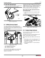
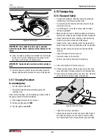
00530
Fig. 13 –
Flow Control Valve
1.
IN
– Oil Supply from Power Source
2.
CF
– Controlled Flow to Conveyor Motor
3.
EX
– Excess Flow to Tank Return
The valve controls oil flow supplied to the conveyor hydraulic
motor. Once set, it maintains constant conveyor speed
regardless of load variation.
Pressurized oil is supplied to the
IN
port on the valve. Flow is
regulated with the valve lever so controlled oil flow exits through
the
CF
port to power the conveyor motor. Excess flow not
required, is diverted to the
EX
port and returns to tank. Return
from the conveyor motor is connected at the
EX
port.
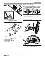
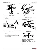
With the conveyor operating, adjust flow control valve to
preferred off-load speed.
1.
Loosen the knob and move the valve handle to desired
speed.
2.
Re-tighten the knob to lock handle at the set speed.
–
+
00470
Fig. 14 –
Flow Control Valve Operation
5.5 Conveyor Angle Indicator
Some site conditions may require parking the conveyor on
ground that slopes up or down.
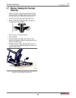
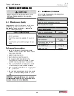
As a guide for a safe conveyor operating inclination, use the
indicator on the right-hand side of the conveyor
When raising, always keep the indicator in white zone on the
decal.
•
White indicates a normal, safe operating angle (0°–35°).
•
Yellow indicates the conveyor is approaching an unsafe
angle (35°–45°). Use caution.
•
Red is an unsafe angle (45°–55°). Lower the conveyor
immediately.
Operating Instructions
CT24
Trailer Firewood Conveyor
20


