


9.8.4 Align the Engine Clutch
The engine mount can move and cause drive-belt misalignment.
1.
Loosen (do not remove) the four engine mount bolts. See
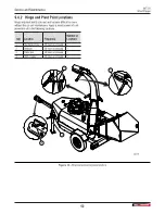
2.
Turn the engine a small amount to adjust the clutch and
align the belt.
3.
Check the drive belt alignment.
For instructions, see
Align the Drive Belt on page 58.
4.
Do one of the following:
• If the belt alignment is correct, continue with step 5.
• If the belt alignment is not correct, do steps 2 to 4
again.
5.
Tighten the four engine mount bolts.
6.
Do steps 3 and 4 again.
7.
Do one of the following:
• If the belt alignment is correct, continue with step 8.
• If the belt alignment is not correct, do steps 1 to 4
again.
8.
Use a calibrated torque wrench to torque the four engine
mount bolts to
19 lbf•ft (25 N•m).
9.
Check the drive belt tension.
For instructions, see
Set the Drive Belt Tension on page
4
3
1
2
02383
Figure 41 –
Align the engine clutch
1. Straight edge
2. Drive belt
3. Rotor sheave
4. Engine clutch flywheel
9.8.5 Align the Rotor Sheave
The rotor sheave can become loose on the shaft and cause
drive-belt misalignment.
The numbers in brackets refer to
1.
Remove the set screw (1) from the sheave (6).
Put the set screw aside. It is necessary for assembly.
2.
Remove the sheave bolts (5).
3.
Thread the sheave bolts into the puller holes (4) on the
sheave hub (2).
4.
In an even pattern, turn each of the bolts clockwise in 1/4
turn increments.
5.
Do step 4 until there is space between the sheave hub and
the sheave, and they can move on the shaft.
6.
Lightly tap the sheave hub with a small rubber mallet to
move it on the shaft and align the drive belt.
7.
Check the drive belt alignment.
For instructions, see
Align the Drive Belt on page 58.
8.
Do one of the following:
• If the belt alignment is correct, continue with step 9.
• If the belt alignment is not correct, do steps 6 to 8.
9.
Remove the sheave bolts from the puller holes.
Turn them counterclockwise in 1/4 turn increments.
10.
Install the sheave bolts in the sheave hub.
11.
Do step 4 until the sheave bolts are tight.
12.
Install and then tighten the set screw (1).
13.
Do step 6 again.
14.
Do one of the following:
• If the belt alignment is correct, continue with step 15.
• If the belt alignment is not correct, do steps 1 to 14.
15.
Use a calibrated torque wrench to torque the three sheave
bolts to
9 lbf•ft (12 N•m)
.
16.
Check the drive belt tension.
For instructions, see
Set the Drive Belt Tension on page
BXT72S
Wood Chipper
Service and Maintenance
59
Summary of Contents for BXT72S
Page 35: ...02220 Figure 20 Set up the machine BXT72S Wood Chipper Operating Instructions 35...
Page 41: ...02225 Figure 26 Transport position BXT72S Wood Chipper Transport 41...
Page 45: ...02227 Figure 30 Storage position BXT72S Wood Chipper Storage 45...
Page 75: ......
Page 76: ...WallensteinEquipment com...