


Service and Maintenance
BX36S
3PH Self-feed Chipper
42
15.8 Rotor Blades
The rotor and ledger blades need to be sharp for the
chipper to perform as expected. Periodic inspection is
recommended. Keep the blades sharp to reduce the
amount of power required during operation. Watch
the sharpness of the blades when processing material
with a lot of sand, soil or dirt mixed with it. Reverse or
sharpen the blades if the cutting edge becomes dull.
The rotor is equipped with 4 blades spaced evenly to
keep the rotor in balance. If one blade needs to be
changed, the one opposite should also be changed.
It is recommended that the rotor blades be removed
from the rotor when sharpening. Always sharpen the
blades at a 45° angle to provide the best cutting effect
as it meets the stationary blade. Be sure to tighten the
blade mounting bolts to their specified torque when
re-installing the blades to the rotor.
CAUTION!
Avoid getting pinched or wedged between the lower
rotor housing and rotor. The rotor is very heavy.
Turn rotor slowly and be aware of hand positioning.
W002
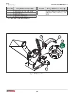
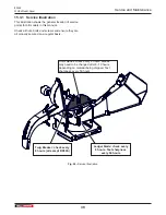
WARNING!
Machine shown with guards removed for
illustrative purposes only. Never operate
machine with guards removed.
W001
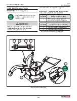
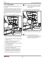
15.8.1 Changing Rotor Blades
Place machine in
Safe Condition.
)
1.
Remove the bolt that secures the upper rotor
housing, and carefully open the rotor housing.
2.
With care, slowly rotate chipper rotor plate until the
rotor lock lines up with lock hole in the rotor plate.
3.
Engage the rotor lock, and ensure it snaps into the
lock hole. Do not allow the rotor lock to snap into
the chipper blade slot, damage to the blade may
result.
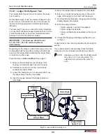
4.
Remove the bolts that hold the rotor blade to the
rotor, remove the blade.
5.
Rotate the blade and reinstall or replace with new
or re-sharpened blade.
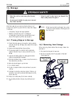
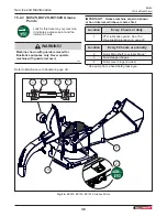
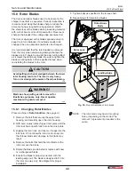
6.
Ensure the blade is properly oriented, with the
leading edge out. The blade is designed to fit into
the rotor one way only. See diagram for proper
installation.
7.
Tighten bolts as specified in the torque chart.
8.
Repeat steps for remaining blades.
Rotor Blade
Bolts
Leading Edge
Rotor Lock
Rotor
Fig. 30 –
Proper orientation of rotor blade
NOTE: The rotor blade may have 4 mounting
holes, depending on the model. The
removal / replacement procedure is the
same.
Summary of Contents for BX36S
Page 1: ...OPERATOR S MANUAL 3PHSelf feedChipper BX36S BX52S BX72S BX102S...
Page 51: ......
Page 52: ...www wallensteinequipment com...


