background image

Specifications

BX52R, BX72R, BX102R

3 PH Roller-feed Chipper

64

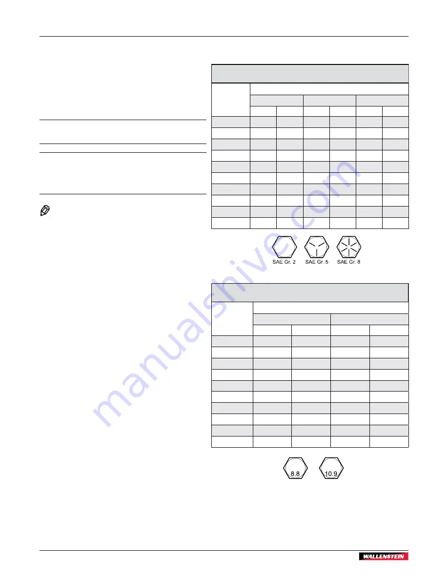
8.2  Common Bolt Torque Values

Checking Bolt Torque

The tables shown give correct torque values for various 
bolts and capscrews. Tighten all bolts to the torque 
values specified in the table, unless indicated otherwise. 
Check tightness of bolts periodically. 

IMPORTANT!  If replacing hardware, use fasteners of 
the same grade.

IMPORTANT!  Torque figures indicated in the table are 
for non-greased or non-oiled threads. Do not grease or 
oil threads unless indicated otherwise. When using a 
thread locker, increase torque values by 5%.

 NOTE:

Bolt grades are identified by their head 
markings.

Imperial Bolt Torque Specifi cations

Bolt 

Diameter

Torque Value

SAE Gr. 2

SAE Gr. 5

SAE Gr. 8

lbf•ft

N•m

lbf•ft

N•m

lbf•ft

N•m

1/4"

6

8

9

12

12

17

5/16"

10

13

19

25

27

36

3/8"

20

27

33

45

45

63

7/16"

30

41

53

72

75

100

1/2"

45

61

80

110

115

155

9/16"

60

95

115

155

165

220

5/8"

95

128

160

215

220

305

3/4"

165

225

290

390

400

540

7/8"

170

230

420

570

650

880

1"

225

345

630

850

970

1320

Metric Bolt Torque Specifi cations

Bolt 

Diameter

Torque Value

Gr. 8.8

Gr. 10.9

lbf•ft

N•m

lbf•ft

N•m

M3

0.4

0.5

1.3

1.8

M4

2.2

3

3.3

4.5

M6

7

10

11

15

M8

18

25

26

35

M10

37

50

52

70

M12

66

90

92

125

M14

83

112

116

158

M16

166

225

229

310

M20

321

435

450

610

M30

1,103

1 495

1,550

2 100

Summary of Contents for 1102R215

Page 1: ...OPERATOR S MANUAL 3 PH Roller feed Chipper BX52R Models S N 152R559 Up BX72R Models S N 172R240 Up BX102R Models S N 1102R215 Up BXR Series Document Number Z97072_En Rev Sep 2020...

Page 2: ...tion Maintenance information contained within the Operator s Manual Keep this manual handy for frequent reference and to pass on to new operators or owners Call your Wallenstein dealer or the distribu...

Page 3: ...rols 25 5 1 Discharge Chute 25 5 2 Discharge Chute Deflector 25 5 3 Feed Roller Control Bar 26 5 4 Feed Roller Flow Control Valve 29 5 5 Easy Start System 29 5 6 Rotor Lock 30 5 9 P3 PULSE Electronic...

Page 4: ...ation and applicable warranty policy and reviewed the manuals Dealer Address City State Province ZIP Postal Code Phone Number 1 2 2 Dealer Inspection Report Check Blade Clearance and Rotor Turns Freel...

Page 5: ...tein product when ordering parts or requesting service or other information The Serial Number Plate location is shown in the illustration Please record the product Model and Serial Number in the space...

Page 6: ...to the operator or explains the operation of a control Product Decals indicate machine model and serial number and other important information VIN NLV MODEL Manufactured by Wallenstein Equipment Inc...

Page 7: ...also be used to alert against unsafe practices CAUTION Indicates a potentially hazardous situation that if not avoided may result in minor or moderate injury It may also be used to alert against unsaf...

Page 8: ...es certain illustrations in this manual may show an assembly with a safety shield removed for clarity However equipment should never be used in this condition Replace any safety sign or instruction si...

Page 9: ...ched can often be noisy enough to cause permanent partial hearing loss Always wear hearing protection if the noise in any area you work in exceeds 80 dB Noise over 85 dB on a long term basis can cause...

Page 10: ...ining the sign off sheet provided below can be used Make periodic reviews of Safety and Operation a standard practice for all operators Review again at the startup of every season The design and manuf...

Page 11: ...the potential hazard and the bottom or right hand panel shows the message how to avoid the hazard Hazard How to avoid the hazard Practicing good safety means becoming familiar with safety signs and w...

Page 12: ...feet out of inlet and discharge openings while machine is operating 2 WARNING Risk of serious personal injury if you are caught in the chipper feed rollers Do not step into or place any part of your b...

Page 13: ...g For this chipper it can be up to 121 decibels at close distances Always wear hearing protection when near the operating machine Noise exposure over 85 dB on a long term basis can cause severe hearin...

Page 14: ...gns that are missing or have become illegible Parts that were replaced with a safety decal on them must also have the safety sign replaced Replacement safety signs are available from your authorized D...

Page 15: ...te Untrained operators are not qualified to use the machine Many features incorporated into this machine are the result of suggestions made by customers like you Read this manual carefully to learn ho...

Page 16: ...Upper Housing 6 Toplink Pin 7 Pressure Hose 8 Return Hose 9 Power Take Off PTO Shaft 10 Lower Link Pin RH 11 P3 PULSE option 12 Manual Tube 13 Toplink BX52R BX72R models 14 Feed Hopper 15 Feed Roller...

Page 17: ...eed Chipper Familiarization 17 Fig 6 Components Typical 1 Rotor Lock 2 Twig Breaker 3 Rotor 4 Rotor Knife 5 Ledger Knife 6 Ledger Setting Gauge 7 Toplink Storage Position BX102R models 8 Lower Roller...

Page 18: ...g 7 Winch and Hydraulic Feed Roller Lift Options BX102RP only 1 Hydraulic Winch 2 Hydraulic Winch Control Valve 3 Winch Gear Engage Disengage Lever 4 Hydraulic Feed Roller Lift Control Valve 5 Lift Cy...

Page 19: ...tch lift arms in their full sway position then reverse the tractor up to the chipper The tractor needs to be exactly in line with the mounting points of the chipper otherwise attaching the 3 point hit...

Page 20: ...afety signs on the machine CAUTION Wear suitable eye protection when cutting steel tubes 1 Remove the PTO shaft and mount the attachment on the tractor three point hitch 2 Start the tractor and raise...

Page 21: ...the plastic tube with the end of the steel shaft 00943 Fig 15 Marking steel tube 10 Cut the steel tube off at the mark 11 Using the cut off length of plastic tube to mark the remaining cuts repeat th...

Page 22: ...tract 2 inches 50 mm from this measurement Call this measurement B L 2 50 mm B 00944 L Fig 18 Measurement B 4 If the collapsed length A is longer than measurement B from Step 3 the PTO shaft must be s...

Page 23: ...d onto the input PTO Connect the safety chain to the implement so that the shielding does not turn during operation 00866 Fig 21 Locking Pin Button 2 Slide out the end of the PTO shaft up to the tract...

Page 24: ...id binding or pinching then connect them to the tractor couplers The protective caps on the hoses are colored to indicate function red is the pressure line black is return Additionally the return line...

Page 25: ...he handles to turn the chute 3 Release the latch handle and make sure the chute locks into position at the next nearest lock point CAUTION Risk of injury from ejected wood chips Chipper rotor can expe...

Page 26: ...ocked in the STOP position until it is released by the detent reset handle The Feed Roller Control bar on the back of the hopper controls the material feed into the chipper The control bar has four po...

Page 27: ...rward or pulled fully back to either STOP position Push the feed roller control bar fully forward towards the feed table to the maximum detent position to stop the feed rollers 00814 Fig 28 STOP Locke...

Page 28: ...ent position to start the forward feed This is the normal operating position The control bar stays in this position until moved 00819 Fig 30 Forward Feed 5 3 3 Reverse Pull the control bar back to the...

Page 29: ...humb screw 2 2 Move the control lever 1 to the desired position 3 Tighten the thumb screw 00822 2 1 Fig 32 Flow Control Valve 1 Control Lever 2 Thumb Screw 5 5 Easy Start System Easy Start means there...

Page 30: ...n a Safe Condition See page 7 Open the upper housing Turn the lock handle up so that the spring pulls the handle pin into the groove 00857 Fig 34 Rotor Unlocked Position Allow the spring to pull the l...

Page 31: ...tor to recover If it slows below the minimum rotor speed setting P3 auto reverses the feed rollers preventing a stall out Wood material is then pulled away from the rotor giving it the opportunity to...

Page 32: ...vigating through the soft key buttons 2 Soft Key Indicator Icons These icons are displayed directly above the Soft Key Navigation Buttons They indicate your current selection options and are only show...

Page 33: ...he rotor NEUTRAL NEUTRAL amber feed rollers are stopped FORWARD FORWARD green arrows feed rollers are going forward Material in the rollers is pushed into the rotor LOW RPM LOW RPM green arrows with t...

Page 34: ...ect Machine Chose machine model to set the default operating parameters for your machine Enter Password This password protected menu provides access to factory settings Use the Up and Down arrows to c...

Page 35: ...t Speed FEED START SPEED 0000 Sets the rpm point where feed rollers start up Min Rotor rpm MIN ROTOR RPM 0000 Sets the low rpm point where the feed rollers auto reverse If the rotor speed slows down u...

Page 36: ...ettings to factory default values 01234 SETTINGS FEED SETTINGS RESET DEFAULTS DIAGNOSTICS SELECT MACHINE ENTER PASSWORD 01252 ARE YOU SURE YOU WANT TO RESET Fig 47 Reset Defaults Screen Diagnostics sc...

Page 37: ...own arrows to navigate to Select Machine then press Press the Up or Down arrows to find your machine model Press to save your selection and P3 returns back to Settings menu Pressing Home icon exits to...

Page 38: ...iculty climbing over Lift the roller start the material then release the roller to begin feeding When feeding in extremely curved or bushy material use the cylinder down force to hold and help grip th...

Page 39: ...he plunger and swing the Winch Arm Extension up out of its stowed position Release the plunger and lock the arm in the work position 00846 Fig 39 Winch Arm Extension A control valve is used to power t...

Page 40: ...draulic control lever back towards you and hold to wind the rope in Releasing the lever returns it to neutral and the winch stops Push the lever forward to allow the rope to unwind under power Releasi...

Page 41: ...ial Crotchety branches and logs can move in unpredictable ways as they pass through the feed rollers and could cause injuries Large curved pieces should be cut to smaller straighter sections Do not wo...

Page 42: ...te equipment for personal protection is available and being used Check that jewelry loose fitting clothing are not worn Make sure long hair is tied back 6 3 Before Startup 1 Check the hydraulic oil le...

Page 43: ...00811 Fig 52 Discharge Chute Adjustable Ski Height BX52R only The BX52R ski can be adjusted up to 6 15 cm if required to help align the PTO shaft when attaching the chipper to the tractor The PTO shaf...

Page 44: ...idle so material can be backed out 3 Push the control bar forward to the first detent position to start the forward feed The control bar stays in this position until moved 00819 Fig 55 Forward Feed N...

Page 45: ...e chipper P3 PULSE continually monitors rotor speed If the rotor slows down under load below a lower speed setting P3 PULSE auto reverses the feed rollers Wood is then pulled away from the rotor givin...

Page 46: ...ll the material is out and nothing is jammed or wedged between the rollers and the rotor If the chipper is still plugged the jammed material must be removed by hand 5 Open the upper rotor housing and...

Page 47: ...erate machine with guards removed W001 If the chipper is still jammed with material see next steps Chipper Severely Plugged The upper feed roller can be raised to clear the debris between the input op...

Page 48: ...hopper to clear out the debris 17 With the debris cleared extend the Toplink to lower the upper roller back into position 18 Disconnect the Toplink from the bridge shorten it up and reconnect it to i...

Page 49: ...ace the feed table in the stowed position 3 Turn the discharge hood towards the tractor to reduce the width of the machine 4 Clean all debris off the chipper Falling debris could cause problems for ot...

Page 50: ...wash the machine with a pressure washer or water hose to remove all dirt mud or debris 4 Run the machine a few minutes to dry the moisture from inside the machine 5 Move the roller feed control bar t...

Page 51: ...on After completing a service procedure make sure all covers and shields are reinstalled When cleaning any parts do not use gasoline or diesel fuel Use a regular cleanser Always use proper tools in go...

Page 52: ...rform Pre operation check See page 42 Every 50 hours or Annually Check rotor blade sharpness See page 56 Check ledger knife sharpness See page 57 Check twig breaker See page 56 Grease entire machine S...

Page 53: ...oller Pivot Bushing RH 8 Upper Roller Bearing LH 9 Upper Roller Bearing LH 10 Roller Pivot Bushing LH 11 Rotor Main Shaft Rear IMPORTANT Use a hand held grease gun for all greasing Pump one shot of gr...

Page 54: ...er to lift or lower the top feed roller located on top of the feed roller chute There is a pivot point at each end of the cylinder The bridge guard must be removed to access the lower fitting 00880 Fi...

Page 55: ...ce 55 Location Lubricate Hinges and Pivot Points As required 1 Rotor Cover Hinge 2 Discharge Chute Rotate 3 Hood Deflector 4 Feed Table Hinges 5 Feeder Control Bar 6 Control Bar Roller Hinge 7 Clean o...

Page 56: ...e broken shear pins with one the same size Always determine the cause of the problem and correct it before resuming work Shear pins are available from your distributor or dealer 7 6 Twig Breaker Inspe...

Page 57: ...is sheared off at the ledger knife by the rotor blades When the corner of the ledger knife facing the rotor blade rounds over the blade can be removed and re installed with a different corner facing t...

Page 58: ...r knives 1 3 2 00877 Fig 78 Checking ledger knife clearance 1 Rotor Blades 2 Gauge 3 Ledger Knife Adjusting 5 Loosen the securing bolts 1 6 Loosen the jam nuts off on the outside of the ledger knife s...

Page 59: ...ely raise and gain access to the rollers a turnbuckle has been included with the chipper On BX102R models the turnbuckle is stored under the feed table with 2 link pins To raise the upper feed roller...

Page 60: ...hydraulic cylinder to hold up the roller 7 10 Electrical System General IMPORTANT When assembling or replacing wire harnesses apply a thin coating of silicone dielectric grease to the harness connecto...

Page 61: ...pen lower roller clean out and remove debris Jammed debris could freeze in colder weather Obstructed discharge Clear debris from discharge chute Unusual machine vibration while operating Broken or mis...

Page 62: ...unit if required Inspect rotor sensor mount or sheave mounted indicator plate for damage or misalignment Repair or replace Check P3 PULSE unit for output signal Replace unit if required Check harness...

Page 63: ...cm 108 x 64 x 90 275 cm x 163 cm x 228 cm 108 x 85 x 100 270 cm x 215 cm x 253 cm Dimensions Feed table closed 62 x 61 x 74 158 cm x 155 cm x 188 cm 83 x 56 x 90 211 cm x 143 cm x 228 cm 85 x 71 x 100...

Page 64: ...locker increase torque values by 5 NOTE Bolt grades are identified by their head markings Imperial Bolt Torque Specifications Bolt Diameter Torque Value SAE Gr 2 SAE Gr 5 SAE Gr 8 lbf ft N m lbf ft N...

Page 65: ...tor body and tighten the swivel nut with the second Torque to values shown If a torque wrench is not available use the FFFT Flats From Finger Tight method Hydraulic Fitting Torque Tube Size OD Hex Siz...

Page 66: ...he original purchase receipt with any claim This warranty does not cover the following 1 Normal maintenance or adjustments 2 Normal replacement of wearable and service parts 3 Consequen al damage indi...

Page 67: ...ubrication 55 Hydraulic Feed Roller Lift 38 Hydraulic Fitting Torque 65 Hydraulic Oil 51 Hydraulic Winch 39 Winch Arm Extension 39 Winch Control Valve 40 Winch Drive 39 I Installing PTO Shaft 23 L Led...

Page 68: ...e Clearance 57 PTO Shaft Maintenance 56 Shear Pin 56 Rotor Blades Changing 56 Twig Breaker 56 Welding on the Chipper 60 Welding on the Machine 60 Setting Rotor Lock 30 Sharpening Rotor Blades 56 Shear...

Page 69: ......

Page 70: ......

Page 71: ......

Page 72: ...www wallensteinequipment com...

Reviews: