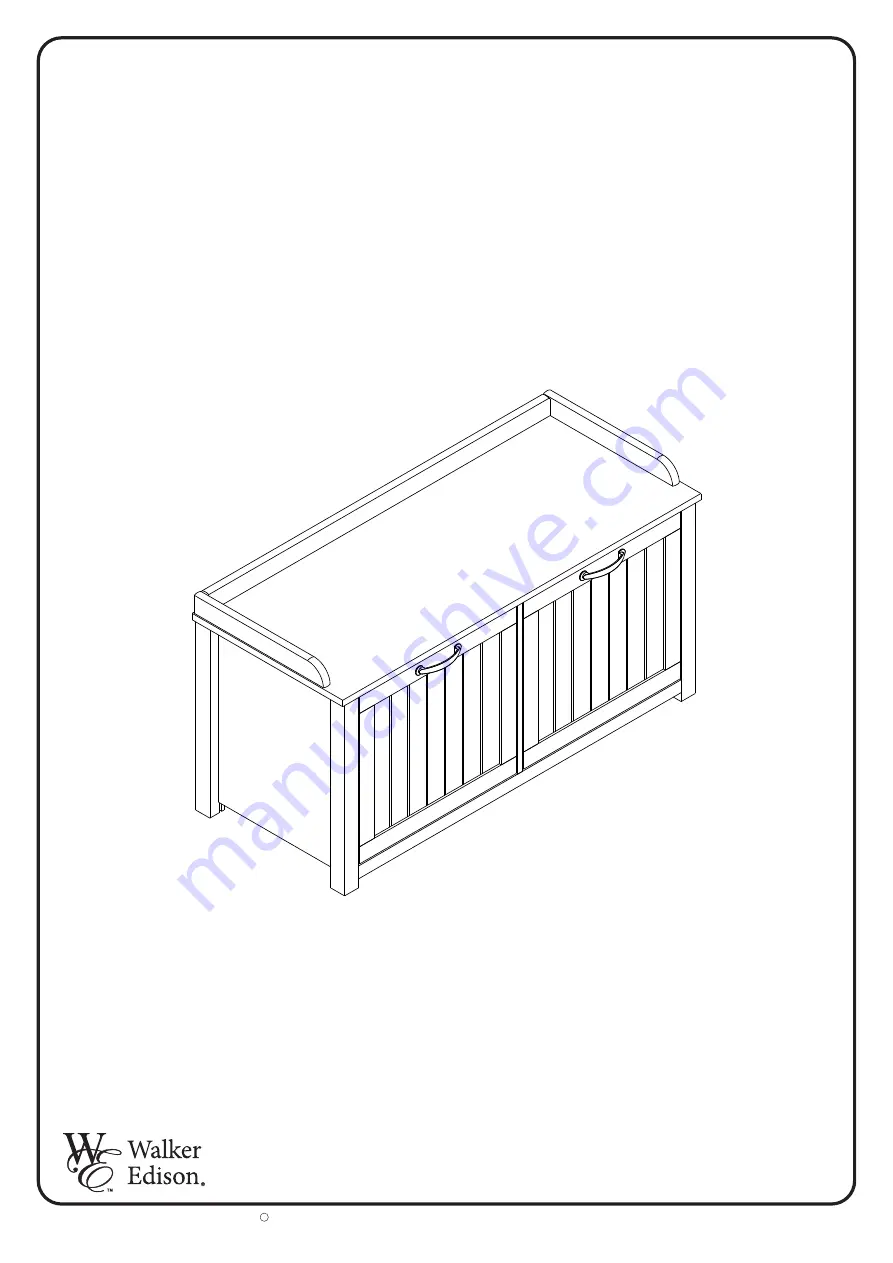
Walker Edison B38L02D Assembly Instruction Manual Download Page 1

P.1

Item #: B38LO2D


Please visit our website for the most current instructions, assembly tips report damage,
or request parts.

www.walkeredison.com

Copyright     2018, by Walker Edison Furniture Co., LLC. All rights reserved.

c

Revised 12/2020

Assembly Instruction

Summary of Contents for B38L02D

Page 1: ...isit our website for the most current instructions assembly tips report damage or request parts www walkeredison com Copyright 2018 by Walker Edison Furniture Co LLC All rights reserved c Revised 12 2...

Page 2: ...P 2...

Page 3: ...P 3 1 2 3 4 5 7 6 8 9 10 11 12 13 14 9 15 16...

Page 4: ...ock 15 pcs 15 pcs 5 5x28mm Cam Bolt 4 0x3 mm 0 3 0x16 mm 18 pcs 8 0x30 mm 02 pcs Knob 13 pcs 3 5x16 mm 22 pcs 3 5x20 mm 02 pcs D H J K E I G F M4x22mm 04 pcs 04 pcs 02 pcs Washer Support 01 pc L Magne...

Page 5: ...01 pc 02 pcs 01 pc M N O Jamb Hinge 02 pcs P 5 5x25 mm 3 5x20 mm Q 02 pcs R 02 pcs S 02 pcs T 02 pcs U 01 pc P 5...

Page 6: ...into part 1 2 3 4 6 7 and 8 Step 2 Attach minifix cam lock A and support J to part 2 and 3 Qty 23 H 8 0x30 mm Qty 04 J A Qty 06 A 5 5x28 mm 1 H H 6 8 H 7 2 J 3 A P 6 HH H HH H H H H H H H H A A H A A...

Page 7: ...K in the pre drilled side of part 5 using screw E Fixing hardware M with screw F Attach cam bolt A into part 5 Qty 02 E 3 5x20 mm Qty 02 F 3 5x16 mm Qty 01 M 5 A Qty 01 L1 Qty 02 K Qty 09 A 5 5x28 mm...

Page 8: ...rt 3 4 to part 1 with cam bolt B Attach part 16 to part 1 with screw C Step 6 Secure part 5 to part 2 3 4 using minifix cam bolt B Qty 09 B B B Qty 06 B Qty 02 C 4 0x30 mm 16 C C B B 3 4 5 B B P 8 B B...

Page 9: ...ecure back panel 9 and profile O to body with screws G Secure part 5 to parts 6 7 8 with screw C Qty 09 C 4 0x30 mm 6 8 8 6 C C C C C C C C Qty 01 O Qty 18 G 3 0x16 mm G G G O 9 G G G G G G G G G G G...

Page 10: ...art 4 and 2 Step 10 First secure part 14 to hardware U with screw F Second secure hardware U to part 15 with screw F Attach hardware L2 with screw F Qty 02 S 10 S S Qty 08 F 3 5x16 mm Qty 01 U Qty 01...

Page 11: ...ch hardware N to door 11 with screw F Attach part 11 to body with screw F Insert knob I with screw D Qty 02 N Qty 08 F 3 5x16 mm P 11 11 N FF I D D 11 F F F F F F Qty 01 I Qty 02 D M 4x22 mm 1st 2nd 4...

Page 12: ...part 12 and 13 with screw F Step 12 Insert knob I to part 15 with screw D Attach hardware R with screw P Qty 02 P 5 5x25 mm Qty 01 I Qty 02 D M 4x22 mm Qty 02 R I D D 15 Qty 04 F 3 5x16 mm 13 12 F F F...

Page 13: ...P 13 Step 15 Final Assembly 260 Lbs Step 14 Attach hardware T with screw Q Qty 02 T Qty 02 Q 3 5x20 mm T Q T T 10 Lbs 12 Lbs 02 Lbs...

Reviews: