352-353.805.006
15
Date: 2019-07-02
Mounting the load
The load on the unit can easily be mounted on the bracket using one or more of the ø12mm holes
[
A
] as shown below. Remove the four M8 bolts [
B
] to fully access the mounting bracket.
When using a secondary suspension [
C
] secured behind the mounting bracket, make sure to
minimize the slack in order to avoid collision with the motor gear and the tooth rack behind the
bracket.
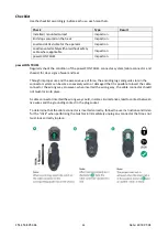
Data link
A DMX 512 data link is required in order to control the product via the Wireless DMX transmitter
[
A
] (ordered separately) or a cable carrier [
E
] to the Track Runner [
B
]. The unit have a 5-pin XLR
connector [
C
] for DMX data output connected to the equipment mounted on the unit [
D
]. The pin-
out on all connectors is pin 1 = shield, pin 2 = (data -), and pin 3 = (data +). Pins 4 and 5 in the 5-
pin XLR connectors are not used but are available for possible additional data signals as required
by the DMX512-A standard.
WARNING! Maximum
bolt length behind the
bracket is 40mm
WARNING! Minimize
slack when using a
secondary suspension
A
B
C
A
B
C
D
Wireless link
200
mm
[7
,874
in
]
50
mm
[1
,969
in
]
OR
Cable carrier
E
Summary of Contents for Track Runner Series
Page 27: ...352 353 805 006 27 Date 2019 07 02 Appendix 3 Power Connectors...
Page 28: ...352 353 805 006 28 Date 2019 07 02...
Page 30: ...352 353 805 006 30 Date 2019 07 02 This page is intentionally left blank...
Page 31: ...352 353 805 006 31 Date 2019 07 02 This page is intentionally left blank...


