


WAGO-I/O-SYSTEM 750
I/O Modules 347
750-882 Media Redundancy ETHERNET Controller
Manual
1.5.0
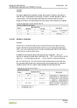
13.2.3.4 3-Phase Power Measurement Module
750-493
The above Analog Input Modules have a total of 9 bytes of user data in both the
Input and Output Process Image (6 bytes of data and 3 bytes of control/status).
The following tables illustrate the Input and Output Process Image, which has a
total of 6 words mapped into each image.
Word alignment is applied.
Table 388: 3-Phase Power Measurement Module
Input Process Image
Offset
Byte Destination
Description
High Byte
Low Byte
0
-
S0
Status byte 0
1
D1
D0
Input data word 1
2
-
S1
Status byte 1
3
D3
D2
Input data word 2
4
-
S2
Status byte 2
5
D5
D4
Input data word 3
Output Process Image
Offset
Byte Destination
Description
High Byte
Low Byte
0
-
C0
Control byte 0
1
D1
D0
Output data word 1
2
-
C1
Control byte 1
3
D3
D2
Output data word 2
4
-
C2
Control byte 2
5
D5
D4
Output data word 3